Adjustable Rear Rotor Discharge Flights

Active Publication Date: 2009-06-04
DEERE & CO
View PDF48 Cites 10 Cited by
  • Summary
  • Abstract
  • Description
  • Claims
  • Application Information

AI Technical Summary

Benefits of technology

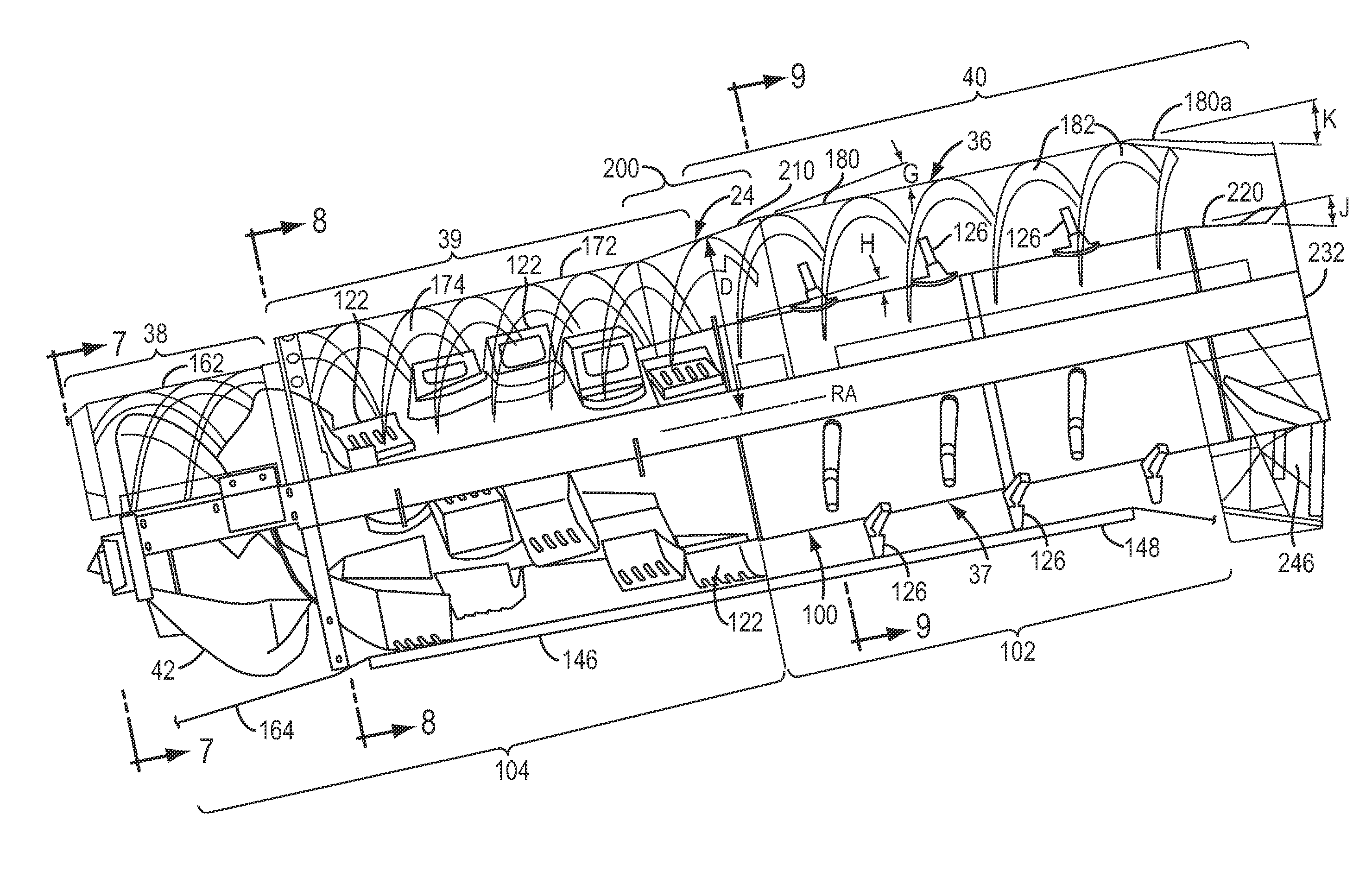
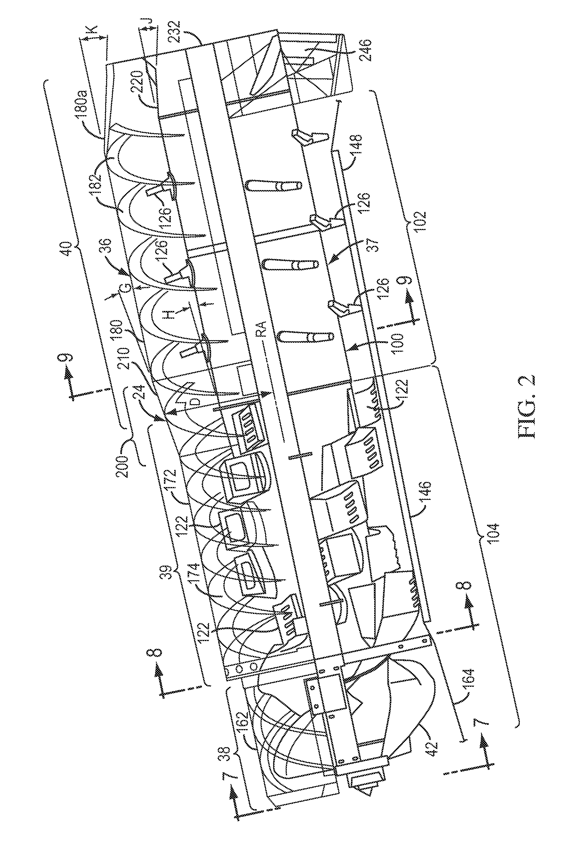
[0012]The discharge vanes each include a base portion permanently mounted to a rear portion of the rotor to that is substantially in registry with a radial outlet of the rotor housing. Onto the vane base portions are mounted adjustable height portions or wings which can selectively adjust the speed of material leaving the rotor area since the speed of material leaving the rotor housing is a function of rotational velocity due to selectively differing swing diameters. This adjustability allows for different material characteristics and required exit velocity and directions. The selectable height

Problems solved by technology

This change in direction leads to loss of angular momentum and velocity which results in straw building up and congestion at the discharge point of the rotor housing.
Extreme hesitation can result in a plug of the discharge of the rotor housing and the

Method used


Image

  • Adjustable Rear Rotor Discharge Flights
  • Adjustable Rear Rotor Discharge Flights
  • Adjustable Rear Rotor Discharge Flights

Examples


Embodiment Construction

[0026]While this invention is susceptible of embodiment in many different forms, there are shown in the drawings, and will be described herein in detail, specific embodiments thereof with the understanding that the present disclosure is to be considered as an exemplification of the principles of the invention and is not intended to limit the invention to the specific embodiments illustrated.

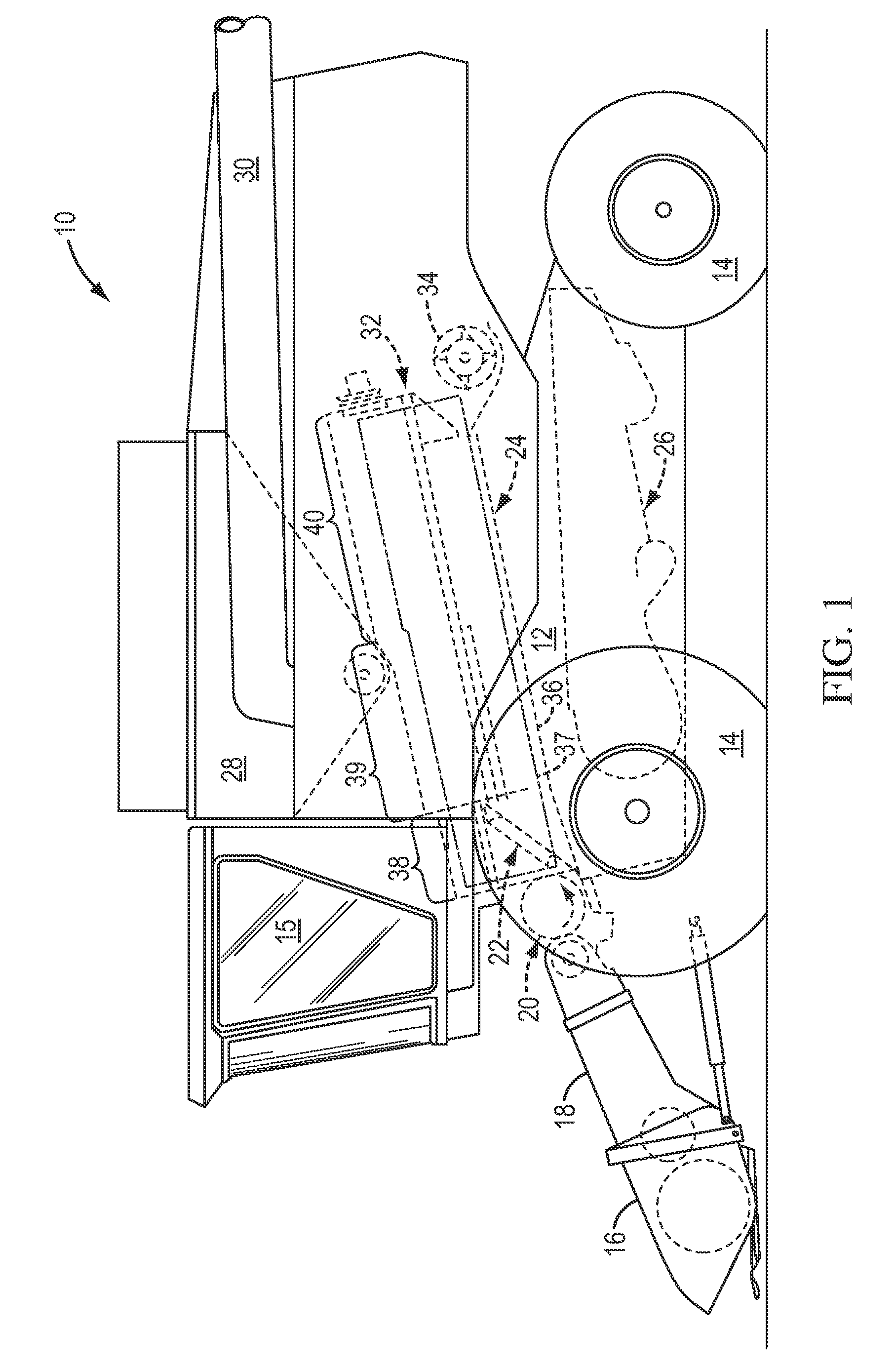
[0027]FIG. 1 shows an agricultural combine 10 comprising a supporting structure 12 having ground engaging wheels 14 extending from the supporting structure. The operation of the combine is controlled from operator's cab 15. A harvesting platform 16 is used for harvesting a crop and directing it to a feederhouse 18. The harvested crop is directed by the feederhouse 18 to a beater 20. The beater directs the crop upwardly through an inlet transition section 22 to the axial crop processing unit 24.

[0028]The crop processing unit 24 threshes and separates the harvested crop material. Grain and chaff fa...


PUM


Abstract

An improved threshing and separating mechanism for a combine that includes an elongated rotor mounted for rotation about a rotor axis within a rotor housing on the combine. The rotor has a threshing portion and a separating portion. The housing has a threshing section and a separating section corresponding to the threshing portion and the separating portion. The housing surrounds the rotor and is spaced from the rotor to form an annular space between the rotor and the housing for crop material to flow through in an axial crop flow direction from an inlet end of the housing to an outlet end of the housing. A rear portion of the rotor tube includes one or more discharge flights or vanes that are adjustable in height and assist in discharging material through the outlet of the rotor housing. The discharge vanes work in conjunction with the vanes in the top covers of the rotor housing.

Description

[0001]This application claims the benefit of U.S. provisional patent application Ser. No. 61 / 004,881 filed on Nov. 29, 2007.FIELD OF THE INVENTION[0002]The invention relates to rotors and housings for axial rotary agricultural combines.BACKGROUND OF THE INVENTION[0003]Agricultural combines are large machines that harvest, thresh, separate and clean an agricultural crop. The resulting clean grain is stored in a grain tank located on the combine. The clean grain can then be transported from the grain tank to a truck, grain cart or other receiving bin by an unloading auger.[0004]Rotary combines have one or two large rotors for threshing and separating the harvested crop material. In most rotary combines the rotor or rotors are arranged along the longitudinal axis of the machine. These rotors are provided with an infeed section for receiving harvested crop material, a threshing section for threshing the harvested crop material received from the infeed section and a separating section fo...

Claims


Application Information

Patent Timeline
IPC IPC(8): B02B3/06A01D41/02
CPCA01F7/067
Inventor POPE, GLENNBRUNS, AARON
Owner DEERE & CO
Why Eureka
Try Eureka