Optical material and method for modifying the refractive index

a technology applied in the field of optical materials and refractive indexes, can solve the problems that most patients undergoing cataract surgery will not enjoy optimal vision, and achieve the effect of little or no scattering loss

Active Publication Date: 2009-06-04
UNIVERSITY OF ROCHESTER
View PDF9 Cites 41 Cited by
  • Summary
  • Abstract
  • Description
  • Claims
  • Application Information

AI Technical Summary

Benefits of technology

[0009]The invention is also directed to an optical device comprising an optical polymeric material with select regions that have been irradiated with a focused, visible or near-IR laser having a pulse energy from 0.05 nJ to 1000 nJ. The irradiation results in the formation of refractive structures characterized by a change in refractive index, and which exhibit little or no scattering loss and no significant differences in the Raman spectrum with respect to the non-irradiated optical, polymeric material.

Problems solved by technology

Unfortunately, due to errors in measurement, variable lens positioning or wound healing, most patients undergoing cataract surgery will not enjoy optimal vision without some form of vision correction following the surgery (Brandser et al., Acta Opthalmol Scand 75:162 165(1997); Oshika et al., J Cataract Refract Surg 24:509 514(1998).
Because the power of present IOLs cannot be adjusted post-implantation, the patient typically must use additional corrective lenses such as eye glasses or contact lenses.

Method used


Image

  • Optical material and method for modifying the refractive index
  • Optical material and method for modifying the refractive index
  • Optical material and method for modifying the refractive index

Examples


example 1

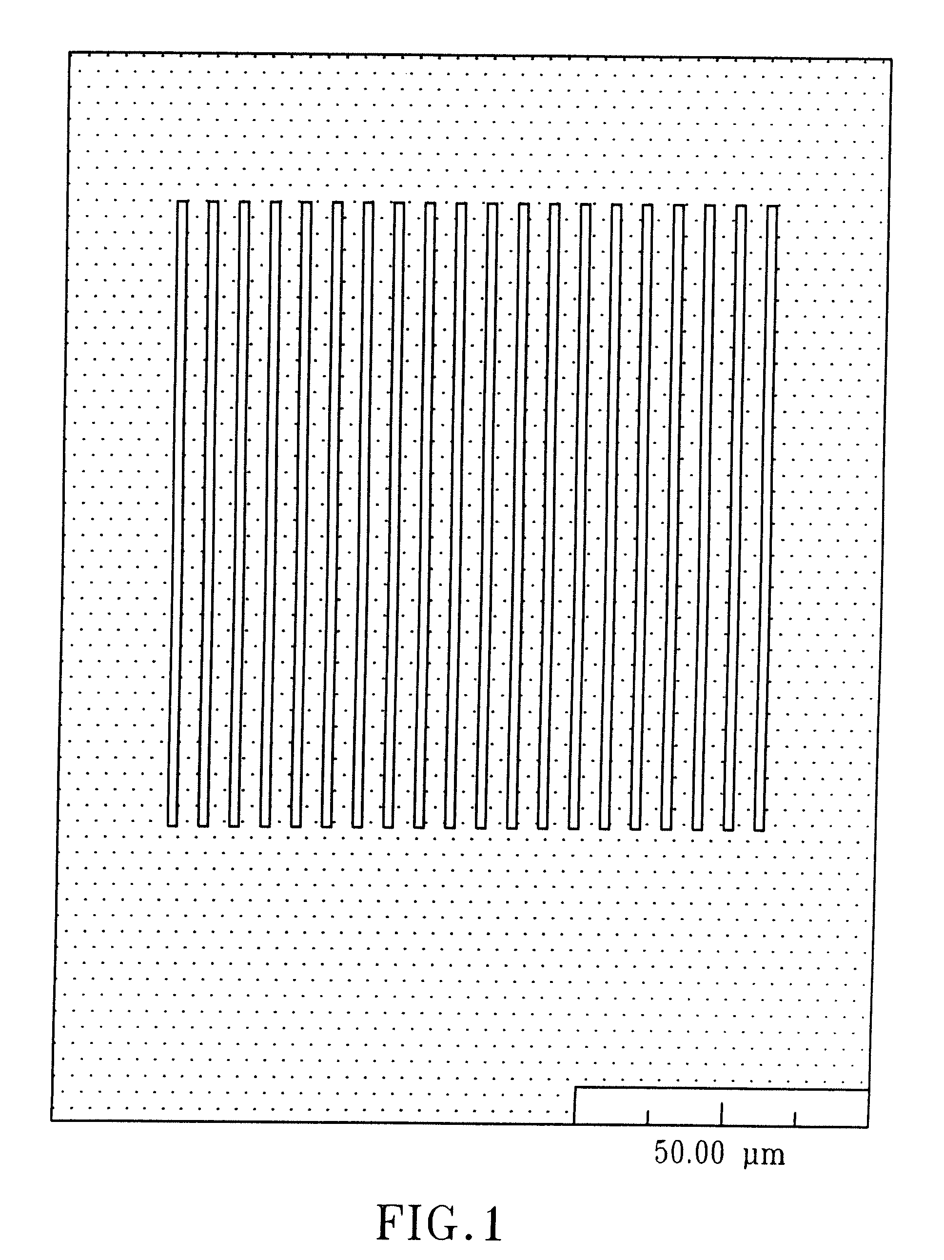
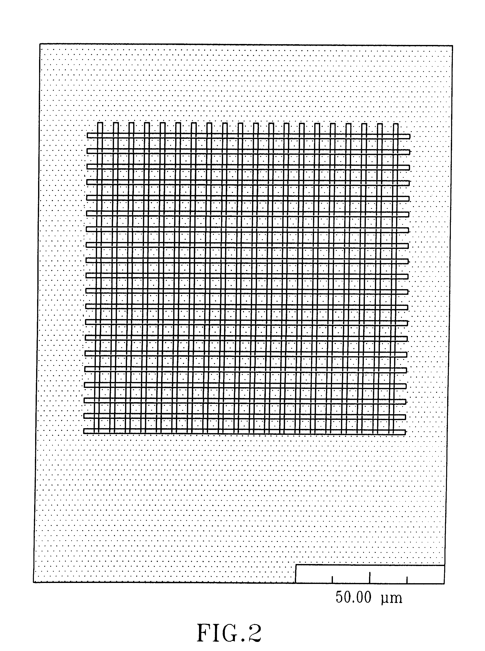
Forming Structures in Optical Polymeric Materials

[0091]The optical system described was used to form line structures in select regions of optical materials. Experiments were conducted with three polymeric materials (Bausch & Lomb Incorporated, Rochester, N.Y.): PV2526-164, RD1817, and HEMA B. PV2526-164 is a silicone-containing hydrogel that can absorb about 36% (by total weight). RD 1817 is a hydrogel copolymer that comprises about 90% (by weight) N-vinylpyrrolidone (“NVP”) and about 10% (by weight) 4-t-butyl-2-hydroxycyclohexyl methacrylate and that can absorb about 80% (by weight) water. Its refractive index when hydrated is very close to the index of water. HEMA B is poly(2-hydroxyethyl methacrylate) cross-linked with about 0.9% (by weight) of ethylene glycol dimethacrylate (“EGDMA”), also a hydrogel, which can absorb about 37% (by weight) water. The refractive indices of PV2526-164, RD1817, and HEMA B are 1.422, 1.363, and 1.438, respectively, when they are in the hydrated stat...


PUM

PropertyMeasurementUnit
pulse energyaaaaaaaaaa

Abstract

A method for modifying the refractive index of an optical, polymeric material. The method comprises irradiating select regions of the optical, polymeric material with a focused, visible or near-IR laser having a pulse energy from 0.05 nJ to 1000 nJ. The irradiation results in the formation of refractive optical structures, characterized by a change in refractive index, exhibit little or no scattering loss, and exhibit no significant differences in the Raman spectrum with respect to the non-irradiated optical, polymeric material. The method can be used to modify the refractive index of an intraocular lens following the surgical implantation of the intraocular lens in a human eye. The invention is also directed to an optical device comprising refractive optical structures, wherein the refractive structures are characterized by a change in refractive index, exhibit little or no scattering loss, and exhibit no significant differences in the Raman spectrum with respect to the non-irradiated optical, polymeric material.

Description

[0001]This patent application claims priority to U.S. patent application Ser. No. 11 / 745,746 filed May 8, 2007, which in turn claims priority to U.S. provisional application Ser. No. 60 / 817,027 filed Jun. 28, 2006.[0002]The present invention relates to a method of using a laser to modify the refractive index of an optical device, and the resulting optical device.BACKGROUND OF THE INVENTION[0003]In general, there are two types of intraocular lenses. One type replaces the eye's natural lens, usually to replace a cataractous lens. The other type is used to supplement an existing lens and functions as a permanent corrective lens. This type of lens (referred to as a phakic IOL) is implanted in the anterior or posterior chamber to correct refractive errors of the eye. In theory, the power for either type of IOL required for enmetropia (i.e., point focus on the retina from light originating at infinity) can be precisely calculated. The power of the implanted lens is selected based on pre-o...

Claims


Application Information

Patent Timeline
Patent Type & Authority Applications(United States)
IPC IPC(8): A61F2/16G02B1/12
CPCA61F2/16B29D11/00461B29D11/023A61F2/14C08J7/123G02C2202/14A61B18/20C08J7/12A61F2/1627A61F2/1635A61F2/1613
Inventor KNOX, WAYNE H.DING, LIKUNZLER, JAY F.JANI, DHARMENDRAPINTO, CANDIDO D.
Owner UNIVERSITY OF ROCHESTER
Why Eureka
Try Eureka