Method and assembly of a pyrolytic carbon component attached to another component

Active Publication Date: 2009-06-04
TORNIER SA SAINT ISMIER
View PDF20 Cites 35 Cited by
  • Summary
  • Abstract
  • Description
  • Claims
  • Application Information

AI Technical Summary

Benefits of technology

[0012]In one embodiment, the engagement surface on the base component includes a maximum dimension and the engagement surface on the pyrolytic carbon component includes a minimum dimension that is less than the maximum dimension on the base member. The pyrolytic carbon co

Problems solved by technology

Yet pyrolytic carbon has the drawback of being poorly adapted as component of an assembly.
On account of its brittleness it is difficult to attach pyrolytic carbon components using fasteners or welding.
Nor can it be drilled as easily as other materials such as metals.
For this reason, very few methods have been proposed thus far for joining a pyrolytic carbon component to another component in an assembly.
The danger exists, therefore, that the pyrolytic carbon will break when it is subjected to additional stresses during use.
Moreover,

Method used


Image

  • Method and assembly of a pyrolytic carbon component attached to another component
  • Method and assembly of a pyrolytic carbon component attached to another component
  • Method and assembly of a pyrolytic carbon component attached to another component

Examples


Embodiment Construction

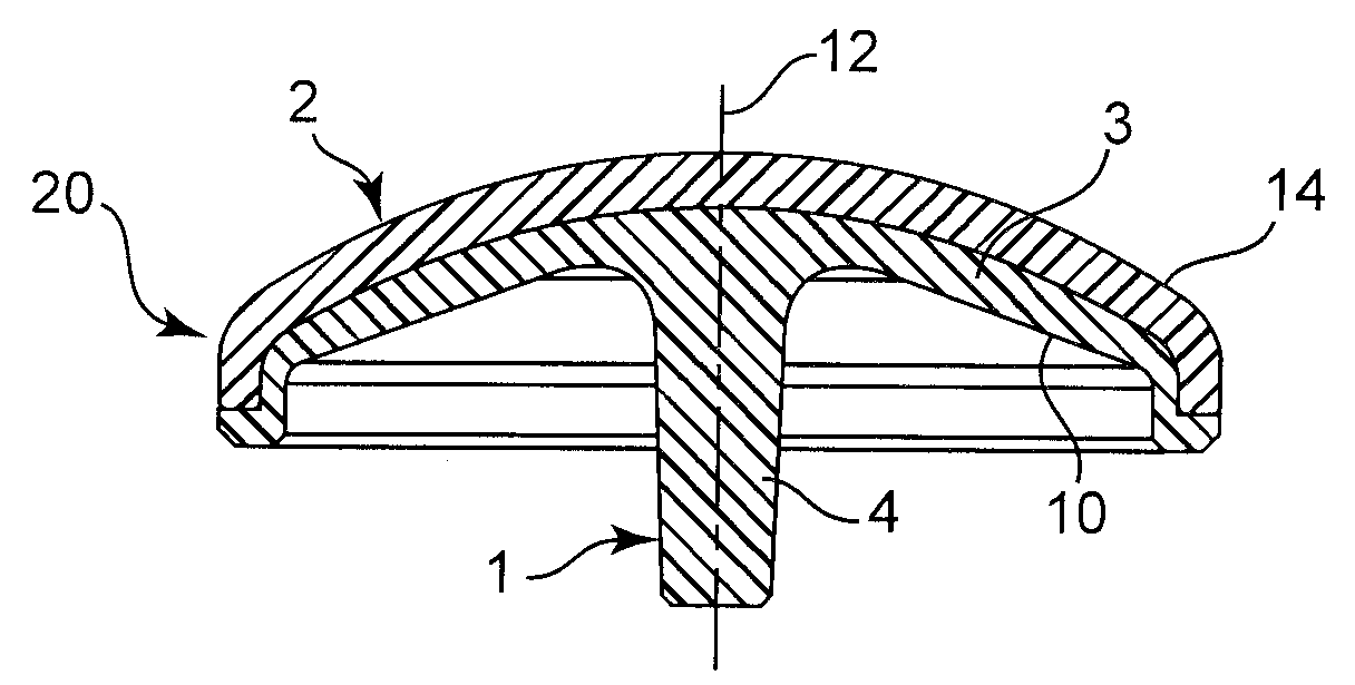
[0020]FIG. 1 illustrates a shoulder prosthesis 20 including a metal base component 1 with a convex outer surface 5 coupled to pyrolytic carbon component 2. The pyrolytic carbon component 2 includes a convex articular surface 14 and a concave inner surface 22 that couples with the outer surface 5 of the component 1.

[0021]In the illustrated embodiment, the convex metal base component 1 includes a cap 3 and a clamping cone 4 extending from the inner surface 10 of cap 3 along assembly axis 12 of component 1. In one embodiment, the clamping cone 4 is intended to be joined with a concave cone of a thread screw (not shown) fixed in the humerus. The base component 1 can be constructed from a variety of materials, such as for example, a cobalt-chromium alloy, ceramics, plastics, or composites thereof. In one embodiment, the base component 1 formed from a single homogeneous piece of material as a unitary component.

[0022]The pyrolytic carbon component 2 is a resurfacing shell that covers and h...


PUM

PropertyMeasurementUnit
Dimensionaaaaaaaaaa
Stress optical coefficientaaaaaaaaaa
Modulusaaaaaaaaaa

Abstract

A prosthetic assembly and a method of assembling same. The prosthetic assembly includes a base component with at least one engagement surface. A pyrolytic carbon component includes at least one engagement surface. The pyrolytic carbon component is elastically deformed to mechanically interlock with the engagement surface on the base component. The pyrolytic carbon component retains at least a portion of the deformation stress created during coupling with the base component.

Description

CROSS REFERENCE TO RELATED APPLICATIONS[0001]This application is a continuation-in-part of International application no. PCT / IB2007 / 001725, with an international filing date of Jun. 25, 2007, entitled Assembly Between a Part Made of Pyrolytic Carbon and Another Part (Assemblage D'Une Piece En Pyrocarbone Et D'Une Autre Piece), which claims priority to French application no. 0652712, filed Jun. 29, 2006, the disclosures of which are all hereby incorporated by reference. This application also claims the benefit of U.S. provisional application No. 61 / 056,326, filed May 27, 2008, entitled Assembly Between a Part Made of Pyrolytic Carbon and Another Part, the disclosure of which is hereby incorporated by reference.FIELD OF THE INVENTION[0002]The present invention relates to a prosthesis with a pyrolytic carbon component attached to a substrate, and to a method of assembling such a prosthesis.BACKGROUND OF THE INVENTION[0003]Pyrolytic carbon is a material that has thus far been used to gr...

Claims


Application Information

Patent Timeline
IPC IPC(8): A61F2/40A61F2/28
CPCA61F2/40A61F2/4003A61F2002/30484A61F2002/30934A61F2002/3411Y10T29/49876A61F2310/00161A61L27/08B23P11/02A61F2002/4007Y10T29/49824A61F2220/0025A61F2002/305
Inventor HASSLER, MICHELREAL, CECILE
Owner TORNIER SA SAINT ISMIER
Why Eureka
Try Eureka