
Piston assembly and connecting rod having a profiled wrist pin bore therefor

a wrist pin and wrist pin technology, applied in the direction of connecting rod bearings, machines/engines, mechanical equipment, etc., can solve the problems of small scuffing of the wrist pin and the connecting rod, reducing the useful life expectancy of the mating bearing surface, and increasing friction

Inactive Publication Date: 2009-06-11
FEDERAL MOGUL CORP
View PDF23 Cites 27 Cited by
  • Summary
  • Abstract
  • Description
  • Claims
  • Application Information

AI Technical Summary

Problems solved by technology

Unfortunately, the increased peak cylinder pressure demands result in an increased pressure distribution across the pivotal joint connection between the small end of the connecting rod and the wrist pin.
The increased pressure between mating bearing surfaces of the connecting rod small end and the wrist pin can result in a reduced useful life expectancy of the mating bearing surfaces.
When the peak cylinder pressures are increased, there are typically two main failure modes.
First, the mating bearing surfaces between the wrist pin and the connecting rod small end scuff due to excessive friction.
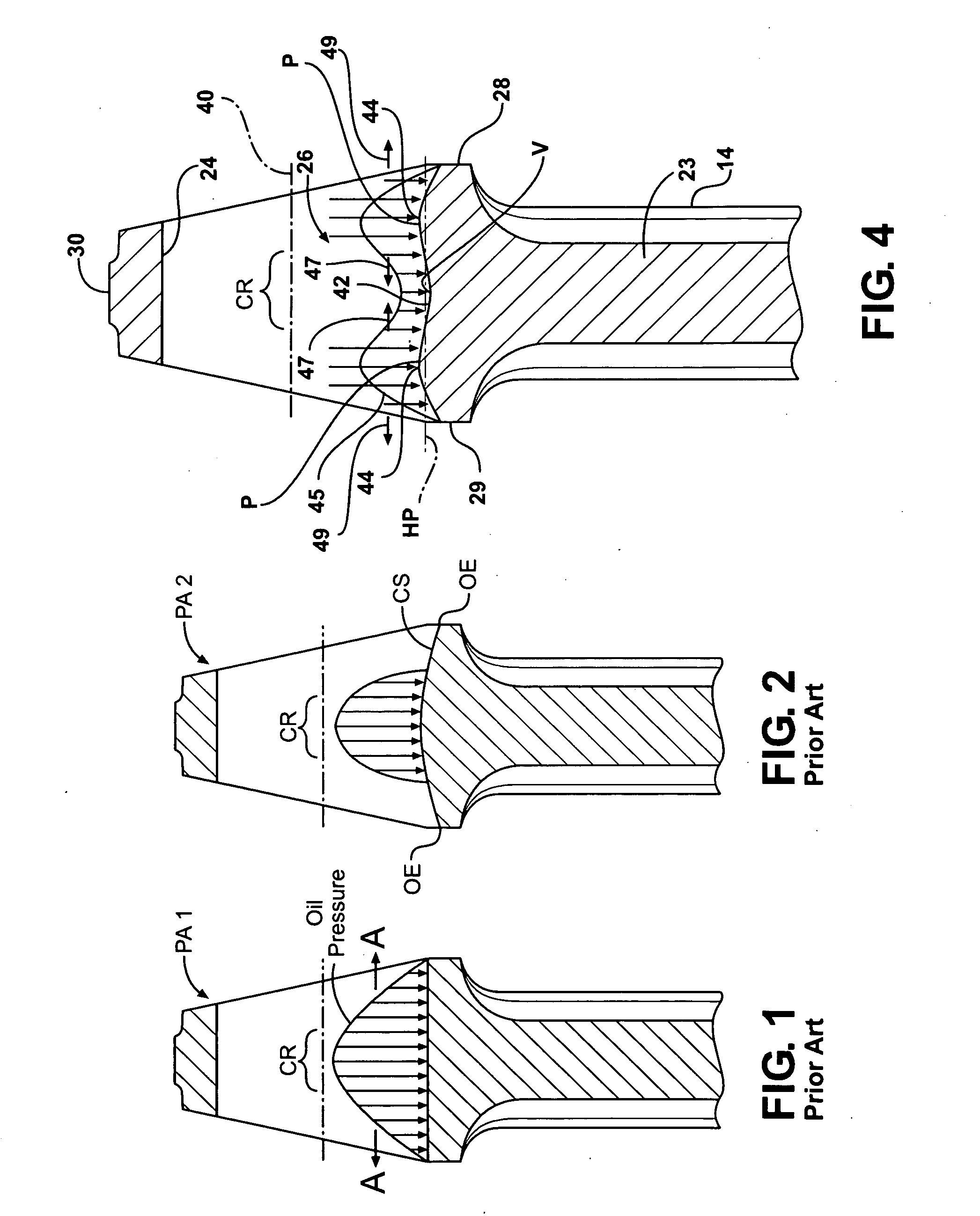
The diminished film of lubrication in the center region CR results in increased friction, which in turn generates heat, and ultimately bearing surface fatigue.
Second, bushings, typically inserted within the connecting rod small end bores, fatigue, such as at their ends or outer edges where stress concentrations are highest.
Unfortunately, these efforts, although reducing the pressures at the outer edges OE, still result in a reduced lubrication over the center region CR due to an ever increased pressure gradient in the center region CR.

Method used


Image

  • Piston assembly and connecting rod having a profiled wrist pin bore therefor
  • Piston assembly and connecting rod having a profiled wrist pin bore therefor
  • Piston assembly and connecting rod having a profiled wrist pin bore therefor

Examples


Embodiment Construction

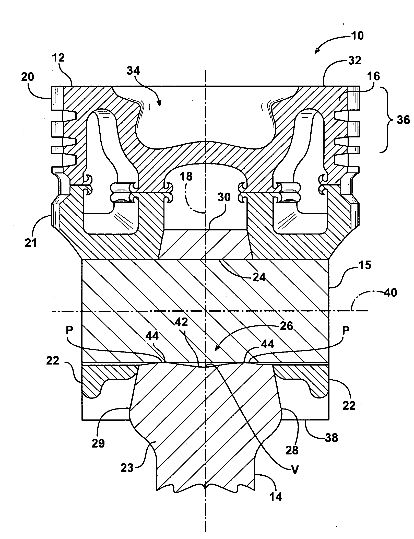
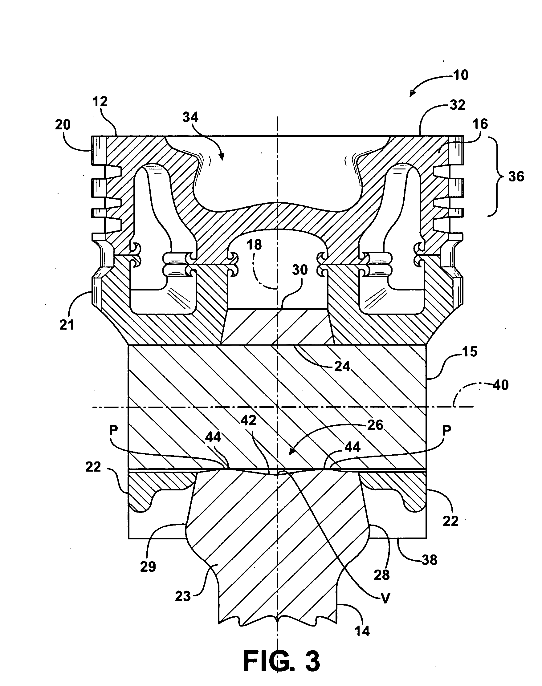
[0018]Referring in more detail to the drawings, FIG. 3 illustrates a piston and connecting rod assembly shown generally at 10 according to one aspect of the invention. The piston and connecting rod assembly 10 includes a piston 12 and a connecting rod 14 configured for operable attachment to one another by a wrist pin 15. The piston 12 has a body 16, either cast or forged, extending along a longitudinal central axis 18 along which the piston 12 reciprocates in a cylinder bore (not shown). The body 16 is represented, by way of example and without limitation, as having an upper crown 20 attached to a lower crown 21 with a pair of pin bosses 22 depending therefrom. The connecting rod 14 has an elongate body 23 extending along a central longitudinal axis, shown here as coinciding with the axis 18, to an end or small end 30 sized for receipt between the pin bosses 22 and to another end (not shown) configured for operable attachment to a crankshaft (not shown). The small end 30 has a wris...


PUM


Abstract

A piston assembly and connecting rod therefor is provided. The connecting rod has an elongate body extending to an end for operable attachment to a piston. The end has a wrist pin bore extending between opposite sides of the body. The wrist pin bore has a wavy profile extending between the sides. The wavy profile has at least one concave surface with a valley extending along a circumferential direction of the wrist pin bore and convex surfaces having peaks extending along a circumferential direction of the wrist pin bore on laterally opposite sides of the valley. The peaks and valleys cooperate to form a smooth load gradient and uniform lubrication flow across the interface region between the wrist pin bore and the wrist pin extending therethrough.

Description

CROSS-REFERENCE TO RELATED APPLICATION[0001]This application claims the benefit of U.S. Provisional Application Ser. No. 61 / 012,530, filed Dec. 10, 2007, which is incorporated herein by reference in its entirety.BACKGROUND OF THE INVENTION[0002]1. Technical Field[0003]This invention relates generally to piston assemblies for internal combustion engines, and more particularly to connecting rods within the assemblies.[0004]2. Related Art[0005]Conventional piston assemblies for use in internal combustion engines generally comprise a crown or head portion which provides a reaction surface for the combustion in a corresponding cylinder of the engine. A pair of laterally spaced pin bosses depend from the piston head and terminate in a pair of coaxial pin bores. A small end of a connecting rod is journaled about a wrist pin, and the wrist pin is journaled within the pin bores.[0006]Modern vehicle engine applications are experiencing increased peak cylinder pressure demands in order to meet...

Claims


Application Information

Patent Timeline
Patent Type & Authority Applications(United States)
IPC IPC(8): F02F3/00
CPCF02F3/00F16C9/04F16C33/10Y02T10/125F02B23/0672F02B23/0693F16J1/16F16C23/041Y02T10/12
Inventor NIGRO, ROBERTO BUENOWANG, KAI
Owner FEDERAL MOGUL CORP
Learn More