

Drill Bit Cutting Structure and Methods to Maximize Depth-0f-Cut For Weight on Bit Applied
a cutting structure and drill bit technology, applied in drill bits, earthwork drilling and mining, construction, etc., can solve the problems of reducing or preventing the penetration of the cutting structure, increasing the wear on the cutting surface, and reducing the effective cutting ra
- Summary
- Abstract
- Description
- Claims
- Application Information
AI Technical Summary
Benefits of technology
Problems solved by technology
Method used
Image

Examples
Embodiment Construction
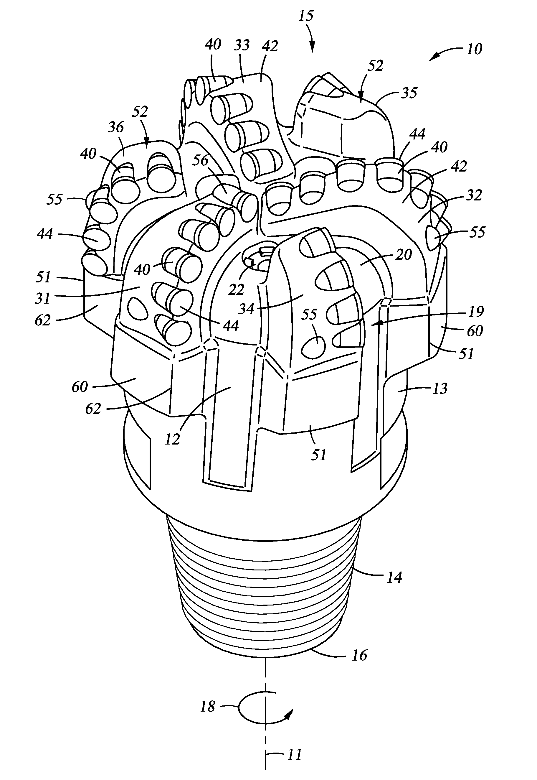
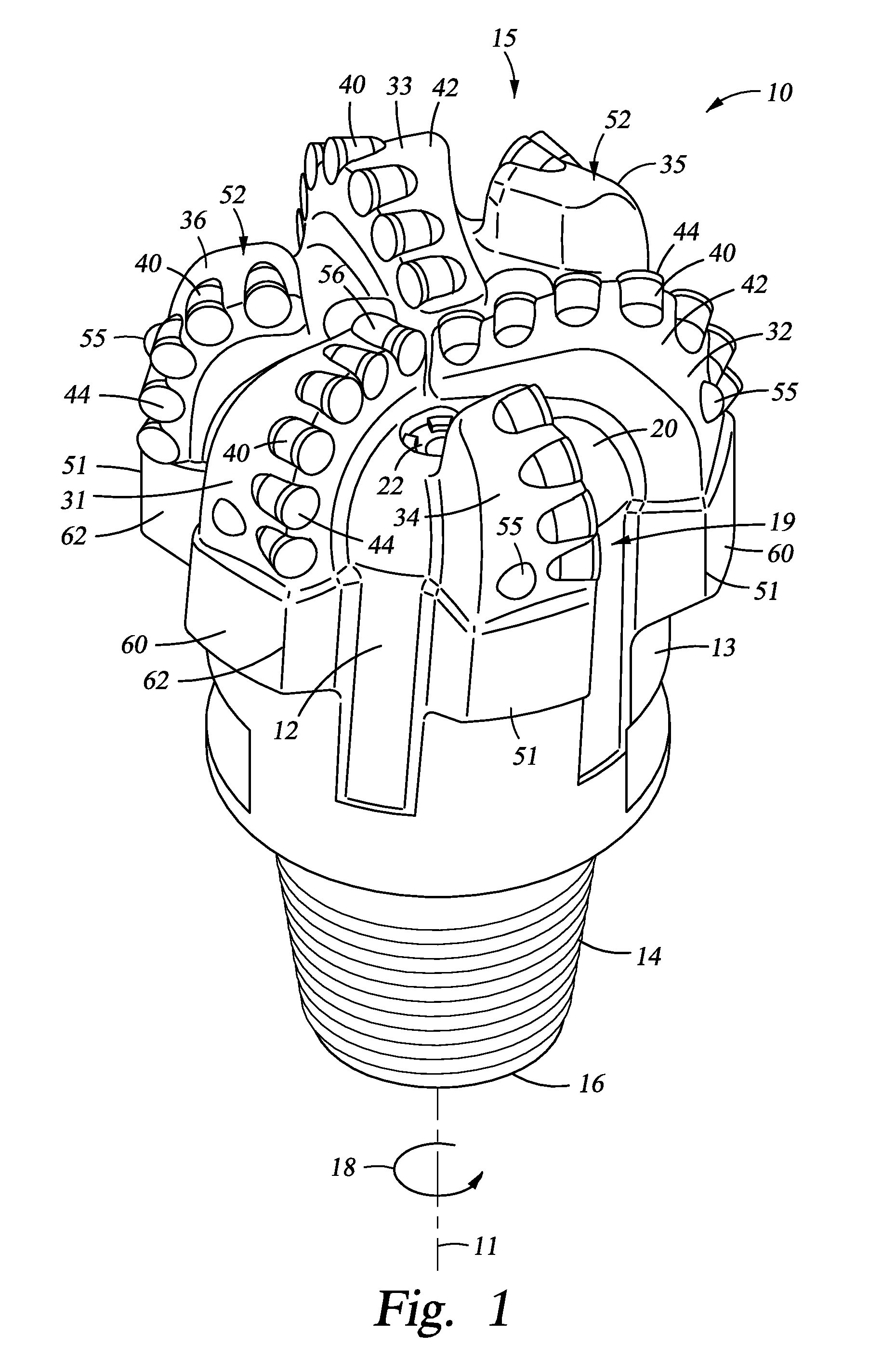
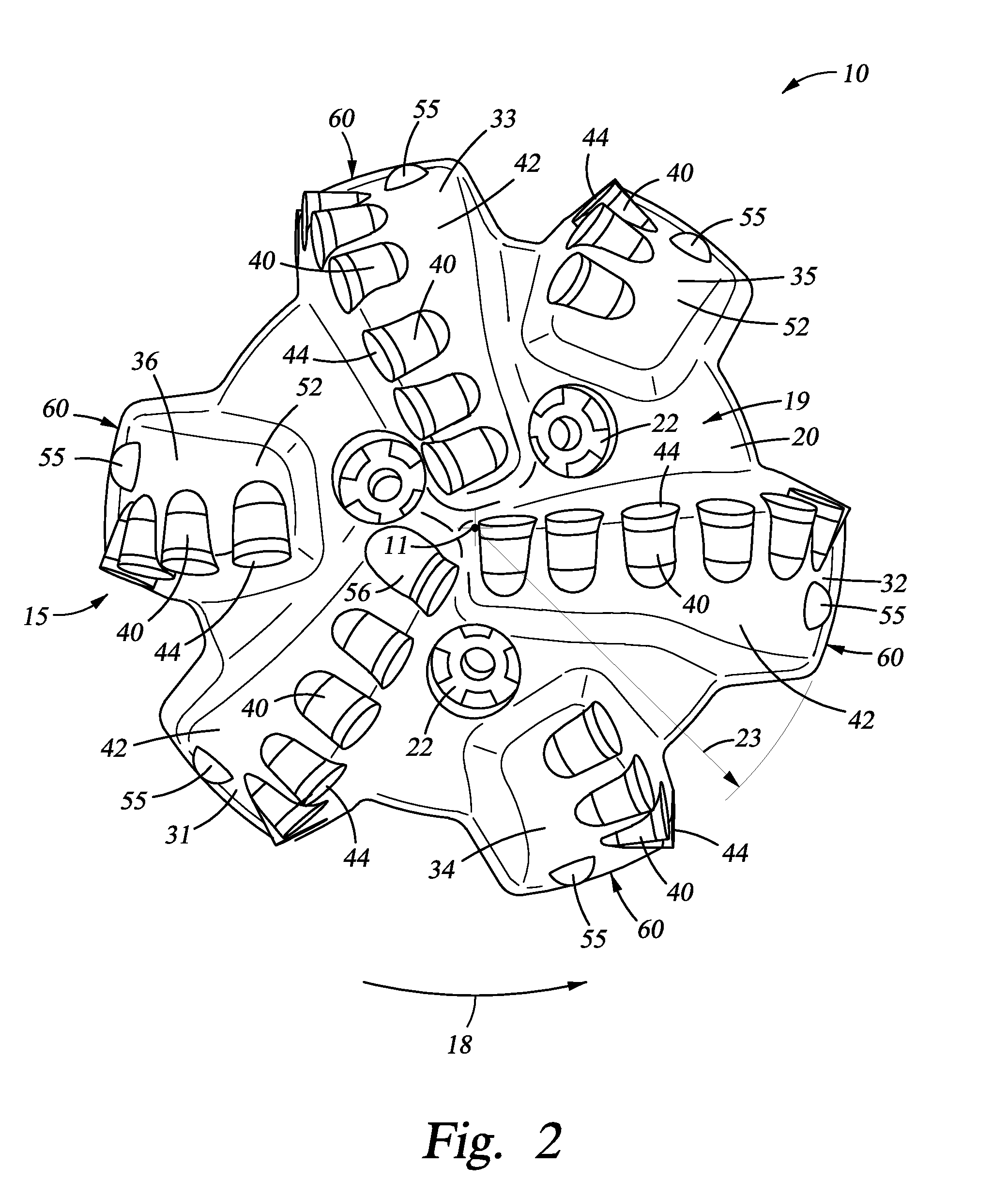
[0015]These and other needs in the art are addressed in one embodiment by a drill bit for drilling a borehole in earthen formations. In an embodiment, the drill bit comprises a bit body having a bit axis and a bit face including a cone region, a shoulder region, and a gage region. In addition, the drill bit comprises a first primary blade extending radially along the bit face from the cone region to the gage region. Further, the drill bit comprises a plurality of primary cutter elements mounted to the first primary blade, each primary cutter element on the first primary blade being mounted in a different radial position. Still further, the drill bit comprises a second primary blade extending radially along the bit face from the cone region to the gage region. Moreover, the drill bit comprises a plurality of primary cutter elements mounted to the second primary blade, each primary cutter element on the second primary blade being mounted in a different radial position. A first primary...
PUM
 Abstract
Description
Claims
Application Information