Method for operation of a position regulator

a position regulator and position technology, applied in the direction of positive displacement liquid engine, fluid pressure control, instruments, etc., can solve the problems of mechanical failure, loss of software implementation characteristics, and negative influence on process or installation

Inactive Publication Date: 2009-06-11
ABB (SCHWEIZ) AG
View PDF16 Cites 11 Cited by
  • Summary
  • Abstract
  • Description
  • Claims
  • Application Information

AI Technical Summary

Benefits of technology

[0012]Exemplary embodiments disclosed herein can develop the known digital pneumatic position regulator such that this neve...

Problems solved by technology

This function is used whenever excessively fast closing or opening of the actuating member which is regulated by the position regulator would have a negative influence on the process or installation.
One example of these negative influences is water-hammering, whose effect may even lead to mechanical failure.
One problem of the known digital pneumatic position regulator is that the characteristics which are implemented in the software are lost as soon as the electrical power supply to the position regulator, and therefore both its microcontroller and the in...

Method used


Image

  • Method for operation of a position regulator
  • Method for operation of a position regulator
  • Method for operation of a position regulator

Examples


Embodiment Construction

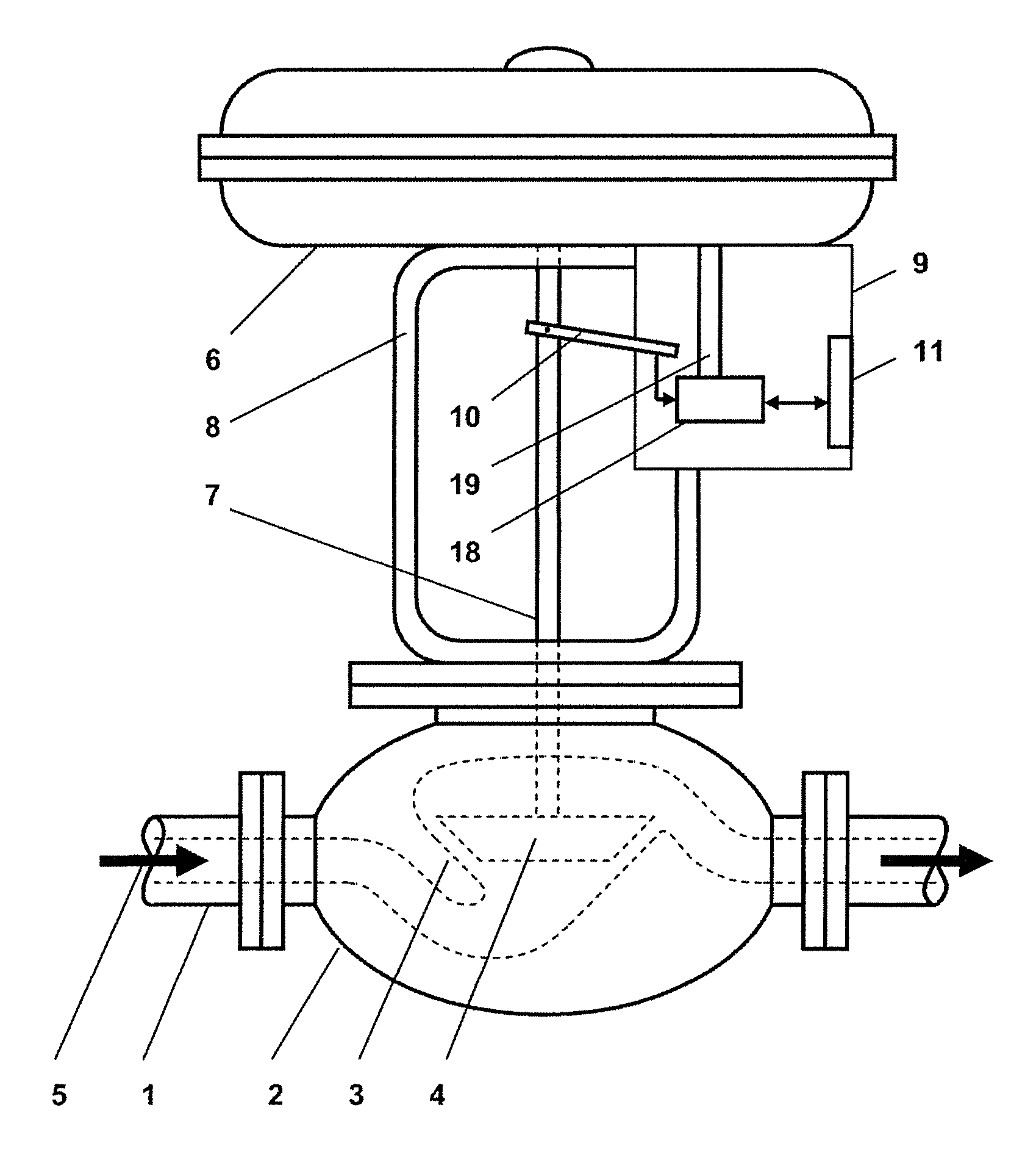
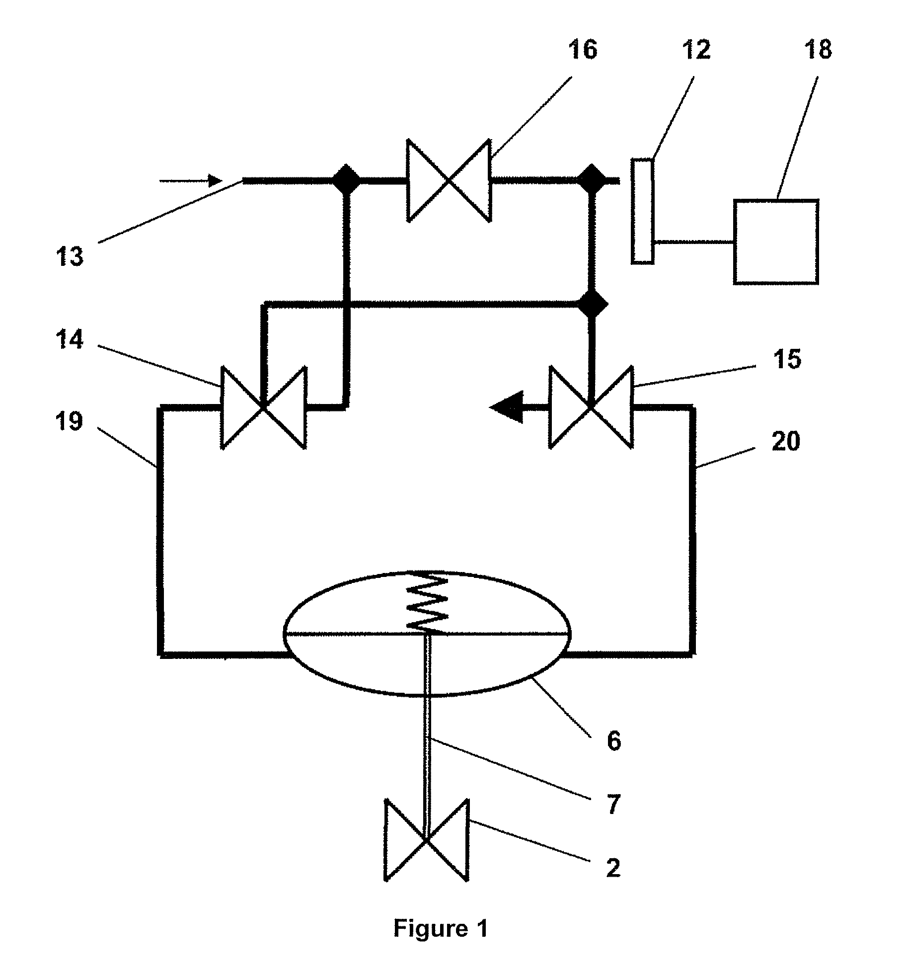
[0019]Against the background of the known digital pneumatic position regulator, the level of the electrical power supply is first of all monitored. If a predeterminable limit value is undershot, the piezo bending bars of the pneumatics are adjusted via the input signals of the pneumatics such that the pneumatically controlled valves, which are subject to a characteristic, of the amplifier are open precisely just so far that a damped movement of the pneumatic drive takes place at the desired movement speed. This results in the actuating member having a movement / time behavior which is equivalent to a ramp function.

[0020]The input signals of the pneumatics that are required for this purpose have already been determined within the firmware function which analyzes the characteristics of the connected fitting.

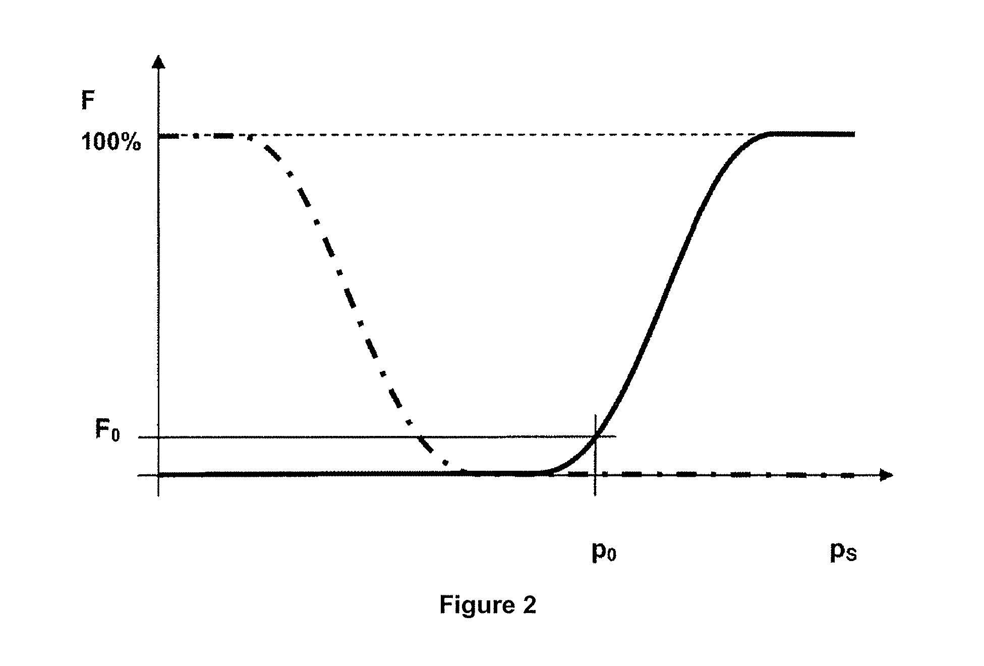
[0021]In this case, the disclosure makes use of the capacitive characteristic of the piezo bending bar of maintaining its shape even without a power supply, for as long as the energy...


PUM


Abstract

The disclosure relates to a method for operation of a position regulator for control of a pneumatic drive for an actuating member in a process installation. The position regulator has a pneumatic system with at least one nozzle/bounce-plate system, in which the bounce plates are in the form of piezo bending bars. For damped ventilation and venting of the pneumatic drive in the event of failure of the electrical power, it is proposed that the level of the electrical power supply be monitored and that, if a predeterminable limit value is undershot, the piezo bending bars of the pneumatics are adjusted via the input signals of the pneumatics such that the pneumatically controlled valves, which are subject to a characteristic, of the amplifier are open precisely just so far that a damped movement of the pneumatic actuating drive takes place to a predeterminable limit position at the desired movement speed.

Description

RELATED APPLICATION[0001]This application claims priority under 35 U.S.C. §119 to German Patent Application No. DE 10 2007 058 518.9 filed in Germany on Dec. 5, 2007, the entire content of which is hereby incorporated by reference in its entirety.TECHNICAL FIELD[0002]A method for operation of a position regulator for control of a pneumatic drive for an actuating member in a process installation is disclosed. In particular, the disclosure relates to the behavior of digital pneumatic position regulators in the event of sudden failure of the electrical power.BACKGROUND INFORMATION[0003]The expression “digital pneumatic position regulator” used in this disclosure represents a mechatronic system which moves a pneumatic drive to a specific position corresponding to one or more input signals. A regulator is not necessarily used for this purpose. In order to operate, the digital pneumatic position regulator requires pressurized gas as auxiliary energy and electrical energy.[0004]The digital...

Claims


Application Information

Patent Timeline
IPC IPC(8): F16K31/12
CPCF04B43/04G05D16/163F16K31/126F15B13/0438Y10T137/2322
Inventor KLEEGREWE, THOMAS
Owner ABB (SCHWEIZ) AG
Why Eureka
Try Eureka