Projection system and projector

Active Publication Date: 2009-06-11
SEIKO EPSON CORP
View PDF11 Cites 12 Cited by
  • Summary
  • Abstract
  • Description
  • Claims
  • Application Information

AI Technical Summary

Benefits of technology

[0030]According to this structure, the one projector has two image forming units and one projection system. The projector included in the projection system having this structure can achieve both highly fine image di

Problems solved by technology

However, resolution of a projector as an image output device for displaying the images produced by such an image input device having high resolution is lower than the resolution of the digital camera or the like.
In the first related art, however, no consideration is given to improvement of visual recognizability of dynamic images.
Thus

Method used


Image

  • Projection system and projector
  • Projection system and projector
  • Projection system and projector

Examples


first embodiment

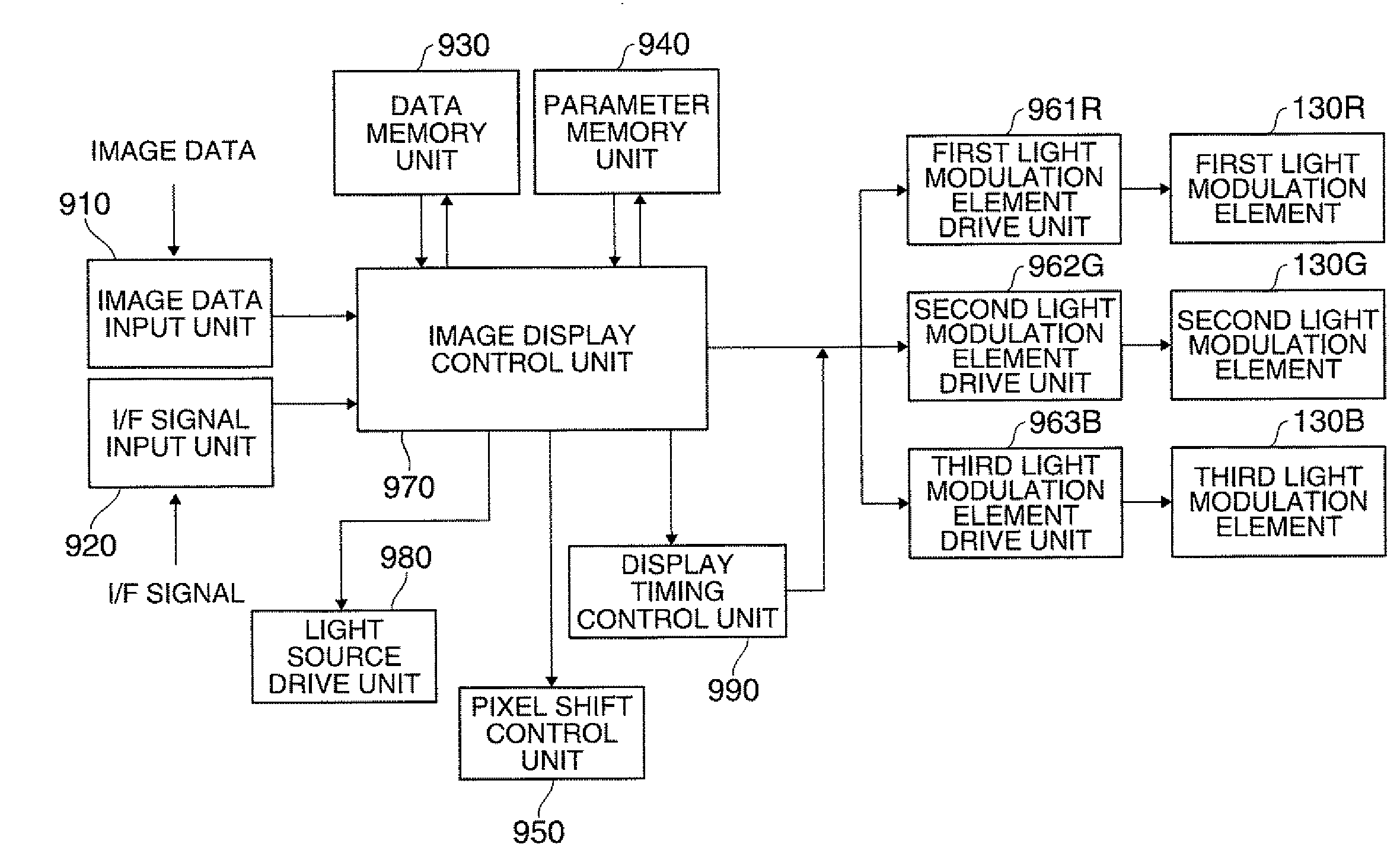
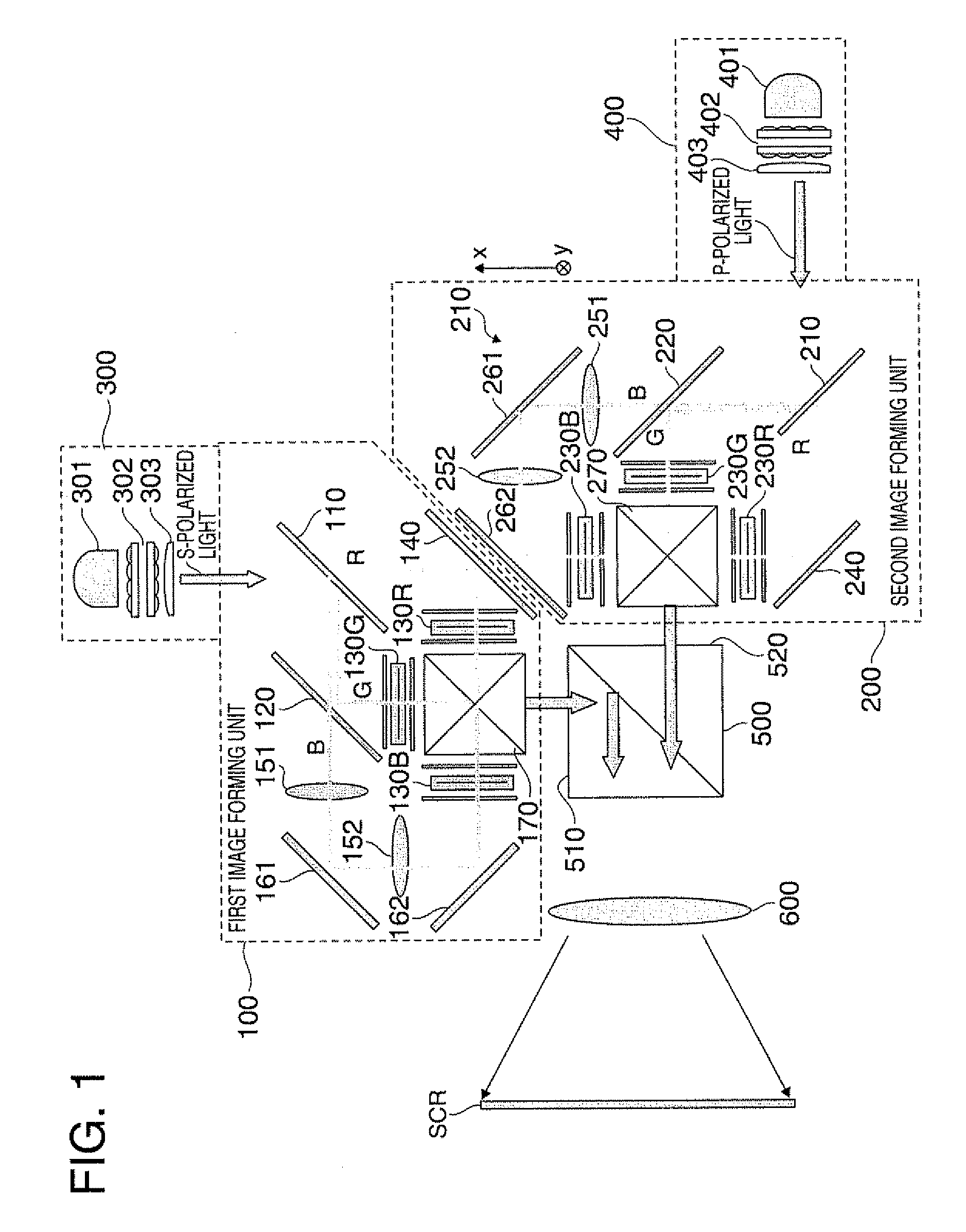
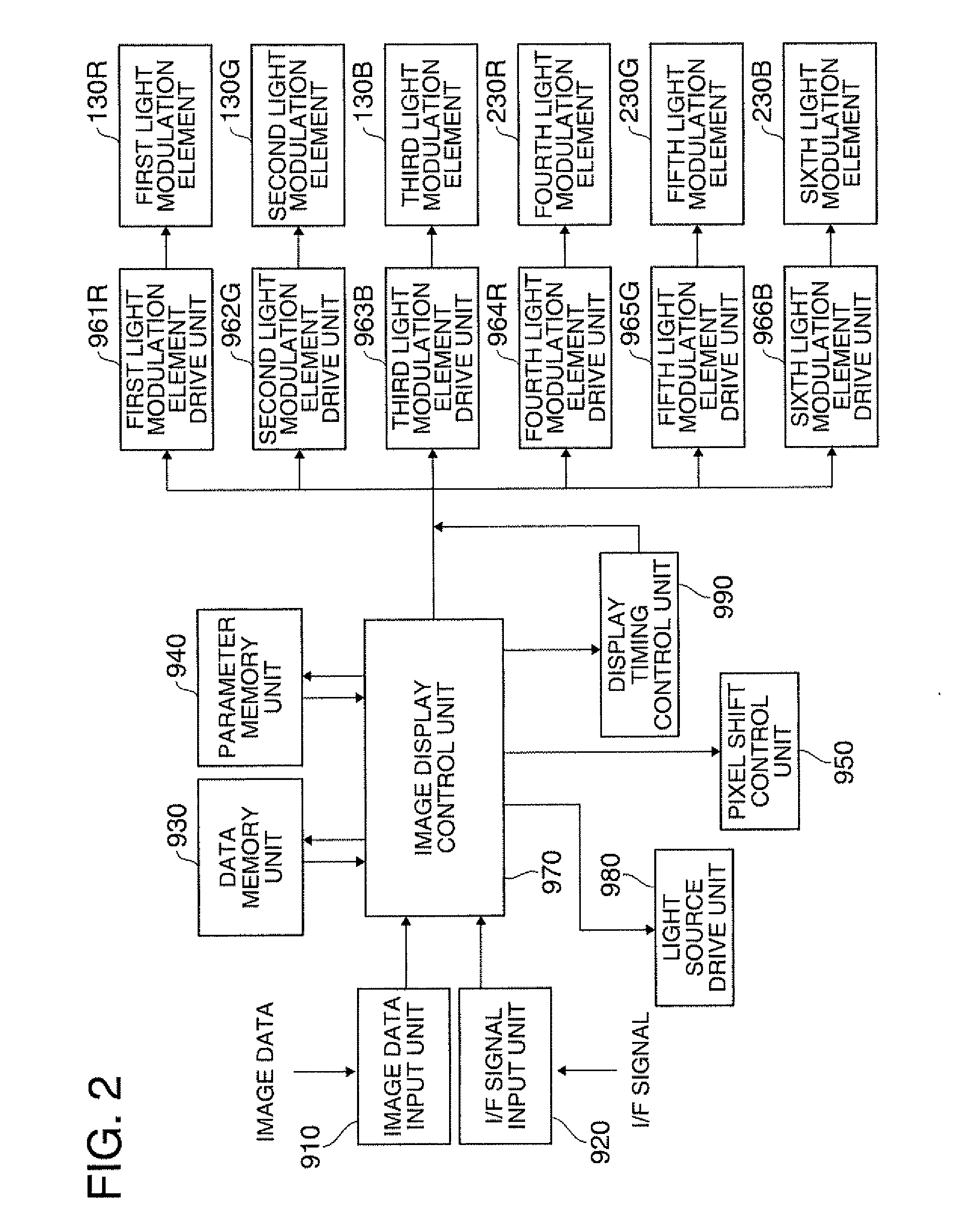
[0042]FIG. 1 schematically illustrates optical systems of a projector included in a projection system according to a first embodiment. As illustrated in FIG. 1, the projector incorporated in the projection system in the first embodiment of the invention (hereinafter abbreviated as “projector according to the first embodiment”) includes image forming units 100 and 200 as two system image forming units (hereinafter referred to as first image forming unit 100 and second image forming unit 200), a first light source device 300 and a second light source device 400 provided in correspondence with the first image forming unit 100 and second image forming unit 200, a polarization combining prism 500 as a polarization combining system for combining image lights (hereinafter referred to as first image light and second image light) emitted from the first image forming unit 100 and the second image forming unit 200, and a projection unit 600 for projecting the image light combined by the polari...

second embodiment

[0079]A projection system according to a second embodiment stacks two images projected from two projectors on a screen for display.

[0080]FIG. 7 illustrates the projection system according to the second embodiment. As shown in FIG. 7, the projection system in the second embodiment is constructed such that images projected from first and second projectors PJ1 and PJ2 can be stacked on the screen SCR. It is assumed that pixel shifting and synchronization shifting are performed on the projection PJ1 side in case of the projection system shown in FIG. 7.

[0081]FIG. 8 schematically illustrates optical systems included in the projector PJ1 of the projection system according to the second embodiment. As illustrated in FIG. 8, the projector PJ1 used in the projection system in the second embodiment (hereinafter referred to as projector PJ1 in the second embodiment) includes the image forming unit 100, the light source device 300, the projection unit 600 which projects image light emitted from...


PUM


Abstract

A projection system includes: a first image forming unit which releases the first image light; a second image forming unit which releases the second image light; a polarization combining system which combines the first image light and the second image light; a projection unit which projects the first image light and second image light combined; a pixel shift control unit which controls a pixel shift unit; a display timing control unit which controls display timing; and an image display control unit having a function which controls the pixel shift control unit and a function which controls the display timing control unit. The image display control unit performs the pixel shifting control when the image is a still image, and performs at least display timing control out of the pixel shifting control and the display timing control when the image is a dynamic image.

Description

BACKGROUND[0001]1. Technical Field[0002]The present invention relates to a projection system and a projector.[0003]2. Related Art[0004]A projector which can easily display large-screen images has been used in a broad application field such as a projection device for presentation, movie, and the like. Recently, resolution of an image input device such as a digital camera has been increasing, which can produce extremely fine images. However, resolution of a projector as an image output device for displaying the images produced by such an image input device having high resolution is lower than the resolution of the digital camera or the like. Moreover, according to a projector using liquid crystals as light modulation elements, the response speed of liquid crystals is relatively low, and thus visual recognizability of dynamic images needs to be improved.[0005]Various technologies for overcoming these problems have been proposed (for example, see JP-A-10-304284 and JP-A-2006-203615). Ac...

Claims


Application Information

Patent Timeline
IPC IPC(8): G09G5/10G03B21/26H04N5/74
CPCG03B21/00G03B33/12G09G3/002G09G3/007G09G3/34G09G3/3406H04N9/3197G09G2310/061G09G2320/0261G09G2320/103G09G2340/0407H04N9/3164H04N9/3188G09G2300/02G03B21/005
Inventor MIYAZAWA, YASUNAGA
Owner SEIKO EPSON CORP
Why Eureka
Try Eureka