Vehicle lamp

a technology for lamps and vehicles, applied in the field of lamps for vehicles, can solve the problems of not providing a suitable light distribution pattern, complicating the optical configuration of each individual lens pattern, and difficult to produce a given distribution pattern or cutoff line forward through the lens, so as to reduce the effect of spherical aberration and simple configuration

Inactive Publication Date: 2009-06-11
STANLEY ELECTRIC CO LTD
View PDF11 Cites 29 Cited by
  • Summary
  • Abstract
  • Description
  • Claims
  • Application Information

AI Technical Summary

Benefits of technology

[0091]The reflection sheet or light shielding sheet may be configured to be retractable from the surface of the light guide plate. When the additional light source produces a second light distribution pattern, this reflection sheet or light shielding sheet can be retracted from the surface of the light guide plate so that the entire light source unit is available for reflection purpose. This can make it possible to create a DRL or other second light distribution pattern which even includes light beams above the horizontal level.
[0092]If the light guide plate is formed with a curve corresponding to an aberration of the projection lens, then the aberration of the project

Problems solved by technology

The lens pattern 3c as used herein, thus, might not provide a suitable light distribution pattern having a desired luminous intensity as a vehicle light such as a headlamp and a vehicle auxiliary lamp such as a fog lamp, or having a bright-dark boundary.
This can complicate the optical configuration of each individual lens pattern 3c.
This can make it difficult to produce a given distribution pat

Method used


Image

  • Vehicle lamp
  • Vehicle lamp
  • Vehicle lamp

Examples


Embodiment Construction

[0132]A description will now be made below to vehicle headlamps of the presently disclosed subject matter with reference to the accompanying drawings in accordance with exemplary embodiments.

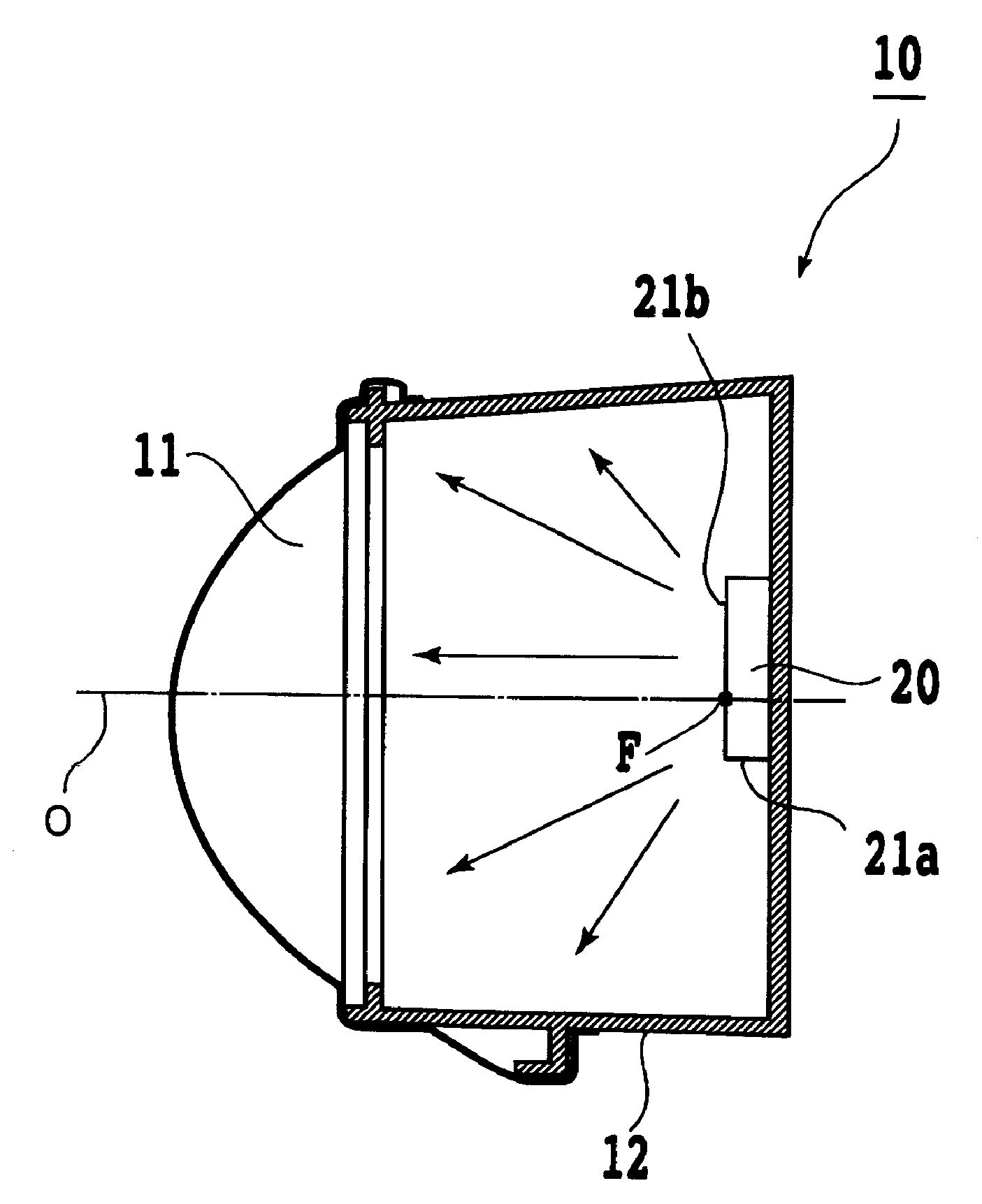
[0133]FIG. 5 shows the configuration of a first exemplary embodiment of a vehicle headlamp made in accordance with principles of the presently disclosed subject matter.

[0134]In FIG. 5, the vehicle headlamp 10 can include a light source unit 20, and a projection lens 11 configured to converge light from the light source unit 20.

[0135]The configuration of the light source unit 20 will be described later. The light source unit 20 can be disposed near the center of the rear end of the box-shaped casing 12, which is opened to the front of the vehicle headlamp 10, so as to emit light forward in the direction of light illumination.

[0136]The projection lens 11 can be made of a convex lens, and is disposed so that its focal position F on the side of the light source unit 20 falls on the light emission su...


PUM


Abstract

A vehicle lamp can include a light source unit including a light guide plate with a light emission surface, and a point or line light source opposed to one end face of the light guide plate. The light guide plate can be made of a transparent plate-like material. A convex projection lens can be configured to focus light emitted from the light source unit and project the light forward in a direction of light illumination. The light guide plate can have a prism array on a rear surface thereof extending with a serrated cross section from the one end face to the opposite end face of the light guide plate, and in a direction parallel with the end face. The prism array can include a plurality of prism surfaces, with each prism surface being obliquely formed so that when light enters the light guide plate from the light source side and impinges thereon, a substantial amount of the light can be totally reflected into small angles of incidence to the emission surface. The projection lens can be disposed such that a focus thereof on a light source unit side is located on the light emission surface of the light guide plate.

Description

[0001]This application claims the priority benefit under 35 U.S.C. § 119 of Japanese Patent Application Nos. 2007-316885 filed on Dec. 7, 2007, 2008-075421 filed on Mar. 24, 2008, and 2008-083858 filed on Mar. 27, 2008 which are hereby incorporated in their entirety by reference.BACKGROUND[0002]1. Technical Field[0003]The presently disclosed subject matter relates to a vehicle lamp such as a headlamp, an auxiliary light, a fog lamp, or other light which is composed of a light source unit using a plurality of point or line light sources and possibly a convex lens. Also, the presently disclosed subject matter relates to a vehicle headlamp which has a daytime running light function.[0004]2. Description of the Related Art[0005]Vehicle lamps using a light guide plate have been known heretofore. Examples thereof include a vehicle lamp or a headlamp as disclosed in Japanese Translation of PCT Patent Application No. 2006-509343 (corresponding to WO 2004 / 052682 or US 2006044825A1), and a com...

Claims


Application Information

Patent Timeline
IPC IPC(8): F21V9/00F21V7/00
CPCF21S48/1154F21S48/1159F21S48/1241G02B6/0038F21S48/1747F21V5/002F21Y2101/02F21S48/1275F21Y2115/10F21S41/143F21S41/145F21S41/147F21S41/151F21S41/24F21S41/265F21S41/663
Inventor AJIKI, SHUICHIMASUYAMA, KOICHISONE, NAOYAKONISHI, SADAYUKITOKO, YASUO
Owner STANLEY ELECTRIC CO LTD
Why Eureka
Try Eureka