Optical disc apparatus, position control method and optical pickup

a technology of optical discs and position control methods, applied in the direction of optical recording/reproducing/erasing methods, instruments, record information storage, etc., can solve the problem of reducing the accuracy of the position control of the focus f, and achieve the effect of improving the level of control accuracy and improving the level of position accuracy

Inactive Publication Date: 2009-06-11
SONY CORP
View PDF2 Cites 9 Cited by
  • Summary
  • Abstract
  • Description
  • Claims
  • Application Information

AI Technical Summary

Benefits of technology

[0024]Thus, the optical pickup according to another aspect of the present invention can form a recording mark at a position separated by a predetermined distance in the layering direction from a formed mark layer in a uniform optical disc by causing a predetermined position control section to control the position of the objective lens and focus the servo light beam on the formed mark layer.
[0025]According to the present invention, a recording mark can be formed at a position separated by a predetermined distance in the layering direction from a formed mark layer in a uniform optical disc by controlling the position of the objective lens so as to focus the servo light beam in the formed mark layer. Thus, the present invention can realize an optical disc apparatus and a position control method that provide an improved level of control accuracy when forming a plurality of layers of recording marks one on the other in an optical disc.
[0026]Additionally, the present invention can realize an optical pickup that can form a recording mark at a position separated by a predetermined distance in the layering direction from a formed mark layer in a uniform optical disc by causing a predetermined position control section to control the position of the objective lens and focus the servo light beam on the formed mark layer so as to provide an improved level of position accuracy when forming a plurality of layers of recording marks one on the other in an optical disc.

Problems solved by technology

Thus, when the accuracy of position control of the lens 6 of the relay lens 5 of the optical disc apparatus 1 is low, there arises a problem of reducing the accuracy of position control of the focus F2.

Method used


Image

  • Optical disc apparatus, position control method and optical pickup
  • Optical disc apparatus, position control method and optical pickup
  • Optical disc apparatus, position control method and optical pickup

Examples


Embodiment Construction

[0037]Now, a preferred embodiment of the present invention will be described in greater detail by referring to the accompanying drawings.

(1) Basic Principle of Controlling the Focus Position

(1-1) Relationship Between Information Light Beam and Servo Light Beam

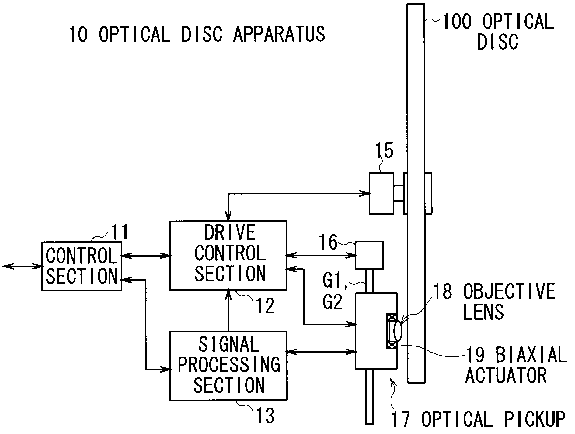
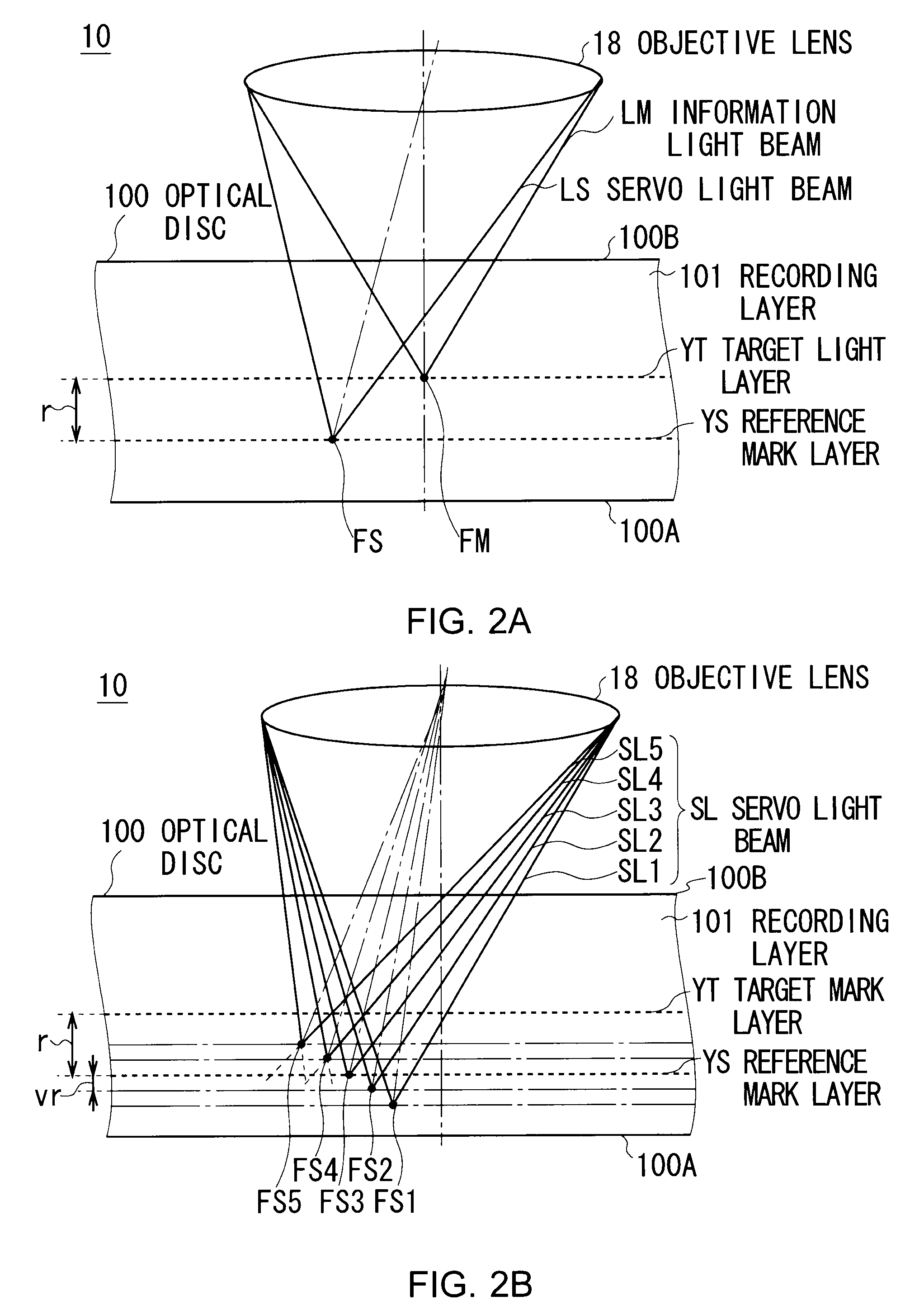
[0038]Firstly, the basic principle of focus position control according to the embodiment of the present invention will be described. As shown in FIG. 2A, information is recorded on an optical disc 100 by irradiating an information light beam LM from an optical disc apparatus 10 onto the optical disc 100 and read out from the optical disc 100 by detecting the information reflected light beam LM that is the information light beam LM reflected by the optical disc 100.

[0039]More specifically, the optical disc apparatus 10 converges the information light beam LM to the inside of the recording layer 101 of the optical disc 100 by means of an objective lens 18 and forms a recording mark RM on the focus FM or reflects the information l...


PUM

PropertyMeasurementUnit
diameteraaaaaaaaaa
wavelengthaaaaaaaaaa
distanceaaaaaaaaaa

Abstract

An optical disc apparatus can make the focus of an information light beam converged by an objective lens agree with a target track of a target mark layer of an optical disc by appropriately predefining the distance between the focus of a servo light beam and that of the information light beam with regard to the direction of the thickness and a radial direction of the optical disc by means of the optical pickup of the apparatus and then operating for focus control and tracking control of the objective lens so as to make focus of the servo light beam converged by the objective lens agree with a reference track of a reference mark layer.

Description

CROSS REFERENCES TO RELATED APPLICATIONS[0001]The present invention contains subject matter related to Japanese Patent Application JP2007-315938 filed in the Japanese Patent Office on Dec. 6, 2007, the entire contents of which being incorporated herein by reference.BACKGROUND OF THE INVENTION[0002]1. Field of the Invention[0003]The present invention relates to an optical disc apparatus, a position control method and an optical pickup. The present invention provides a technique that can suitably be applied to an optical disc apparatus for recording information on a plurality of layers of an optical disc.[0004]2. Description of the Related Art[0005]Known popular optical disc apparatus are mostly designed to irradiate a light beam on an optical disc such as a compact disc (CD), a digital versatile disc (DVD) or a Blu-ray disc (registered trademark, to be referred to as “BD” hereinafter) and reproduce information by reading the reflected light beam.[0006]Such known popular optical disc ...

Claims


Application Information

Patent Timeline
Patent Type & Authority Applications(United States)
IPC IPC(8): G11B7/135
CPCG11B7/00452G11B7/0053G11B7/00736G11B2007/0013G11B7/0938G11B7/1353G11B7/0079
Inventor SAITO, KIMIHIROMIYAMOTO, HIROTAKAHORIGOME, TOSHIHIRO
Owner SONY CORP
Why Eureka
Try Eureka