Duct corner accessory with pivoting flaps

a technology of pivoting flaps and accessories, which is applied in the direction of bends, couplings, siphons, etc., can solve the problems of difficulty in assembling the flaps and disassembly of the flaps, and achieve the effect of convenient assembly

Inactive Publication Date: 2009-06-11
LEGRAND SNC
View PDF6 Cites 5 Cited by
  • Summary
  • Abstract
  • Description
  • Claims
  • Application Information

AI Technical Summary

Benefits of technology

[0012]Compared with the above-mentioned state of the art, the present invention proposes a corner accessory in which the flaps are arranged in such a manner as to make them easier to assemble together, while ensuring that an impact against said flaps does not cause them to be disassembled, regardless of their relative position in use.

Problems solved by technology

Firstly, it is difficult to assemble the two flaps of the accessory together since that requires said flaps to be deformed and requires the studs to be brought into alignment with the respective openings while they are unseen.
Thus, when an impact occurs against said flaps, it can easily cause the studs to escape from said openings and thus cause the flaps to be disassembled.

Method used


Image

  • Duct corner accessory with pivoting flaps
  • Duct corner accessory with pivoting flaps
  • Duct corner accessory with pivoting flaps

Examples


Embodiment Construction

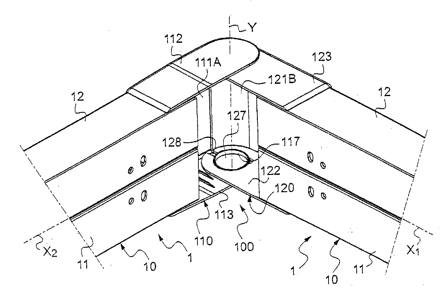
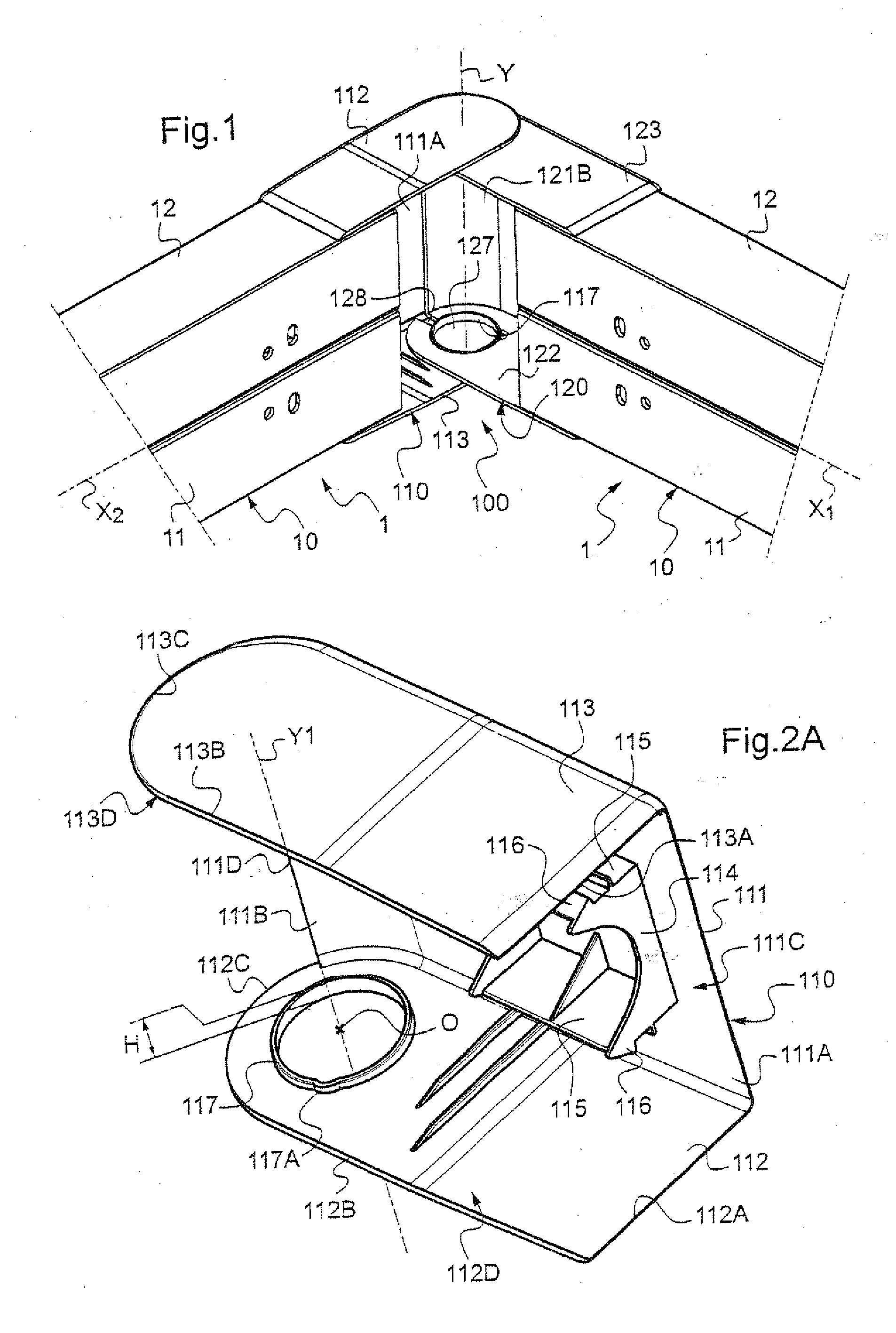
[0029]FIG. 1 shows a corner accessory 100 located at the junction between two ducts 1 extending in different directions X1 and X2.

[0030]The corner accessory 100 shown is an outside corner accessory that is particularly adapted to joining together two ducts 1 that in practice are at a relative angle lying in the range 60 to 95°, and that is preferably equal to 90°.

[0031]With consideration to two walls (not shown) forming a projecting dihedral, the bases 10 of two ducts 1 are each placed flat against respective ones of the two walls, e.g. running along the base of the walls to constitute respective baseboards.

[0032]The bases 10 of the ducts 1 are cut and positioned so as to meet edge to edge in practically touching manner via their back faces so as to form substantially the same projecting angle as is formed between the support walls.

[0033]As can be seen more particularly in FIG. 1, the bases 10 of the ducts 1 are substantially of channel section with respective webs 11 and pairs of p...


PUM


Abstract

The invention relates to a corner accessory for placing at the junction between at least two ducts that extend in different directions, the accessory comprising two distinct flaps, one of which includes a projecting element and the other of which includes a circular opening receiving said projecting element to allow said flaps to pivot about a pivot axis, the circular edge of said opening opening out locally to a straight slot that extends radially relative to the circular edge of said opening and that opens out into a free edge of said flap. According to the invention, said projecting element is a cylindrical wall presenting firstly an outside diameter equal, ignoring clearance, to the inside diameter of said circular opening so that during pivoting of one flap relative to the other, the outside face of said cylindrical wall slides over the edge face of the circular edge of said opening, and presenting secondly a height that varies around its circumference.

Description

TECHNICAL FIELD TO WHICH THE INVENTION RELATES[0001]The present invention relates in general to ducts of the type used, for example, to support, house, and protect various pieces of equipment, such as pieces of electrical equipment, and also to support, house, and protect cables, conductors, pipes, or other pieces of equipment needed for serving said pieces of equipment.[0002]The invention relates more particularly to a corner accessory for placing at the junction between at least two ducts that extend in different directions, the accessory comprising two distinct flaps, one of which includes a projecting element and the other of which includes a circular opening receiving said projecting element to allow said flaps to pivot about a pivot axis, the circular edge of said opening opening out locally to a straight slot that extends radially relative to the circular edge of said opening and that opens out into a free edge of said flap.[0003]A particularly advantageous application of the...

Claims


Application Information

Patent Timeline
Patent Type & Authority Applications(United States)
IPC IPC(8): F16B1/00
CPCH02G3/0608Y10T403/42Y10T403/32401Y10T403/32262F16B2200/67
Inventor WENTS, THIERRY
Owner LEGRAND SNC
Why Eureka
Try Eureka