Fluidic Energy Transfer Devices

a technology of energy transfer device and flue gas, which is applied in the direction of machines/engines, liquid fuel engines, positive displacement liquid engines, etc., can solve the problems of increasing manufacturing complexity and cost, difficult to maintain efficiency, and difficult to control the efficiency of actuators used to drive larger diaphragm pumps. , to achieve the effect of increasing reducing the volume of the chamber

a technology of energy transfer device and flue gas, which is applied in the direction of machines/engines, liquid fuel engines, positive displacement liquid engines, etc., can solve the problems of increasing manufacturing complexity and cost, difficult to maintain efficiency, and difficult to control the efficiency of actuators used to drive larger diaphragm pumps. , to achieve the effect of increasing reducing the volume of the chamber

US20090148320A1Active Publication Date: 2009-06-11AAVID THERMALLOY LLV

Image

  • Fluidic Energy Transfer Devices
  • Fluidic Energy Transfer Devices
  • Fluidic Energy Transfer Devices

Examples


Embodiment Construction

[0161]In this section, descriptions of the embodiments of the present invention are organized under subheadings that describe the forces being applied to the diaphragms or pistons of the present invention. The force designations generally indicate the direction of the force with respect to the diaphragm / piston axis (i.e. axial or radial) and the point of application (e.g. on-center / axis, off-center, or at the clamp point).

Reaction-Drive Topologies

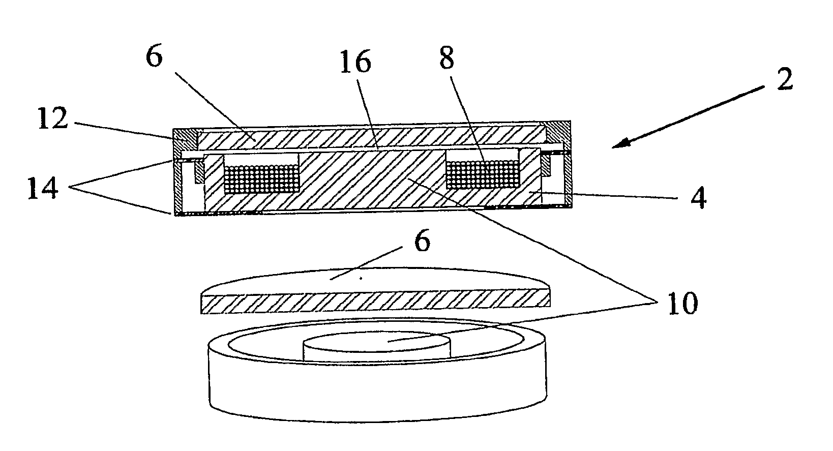
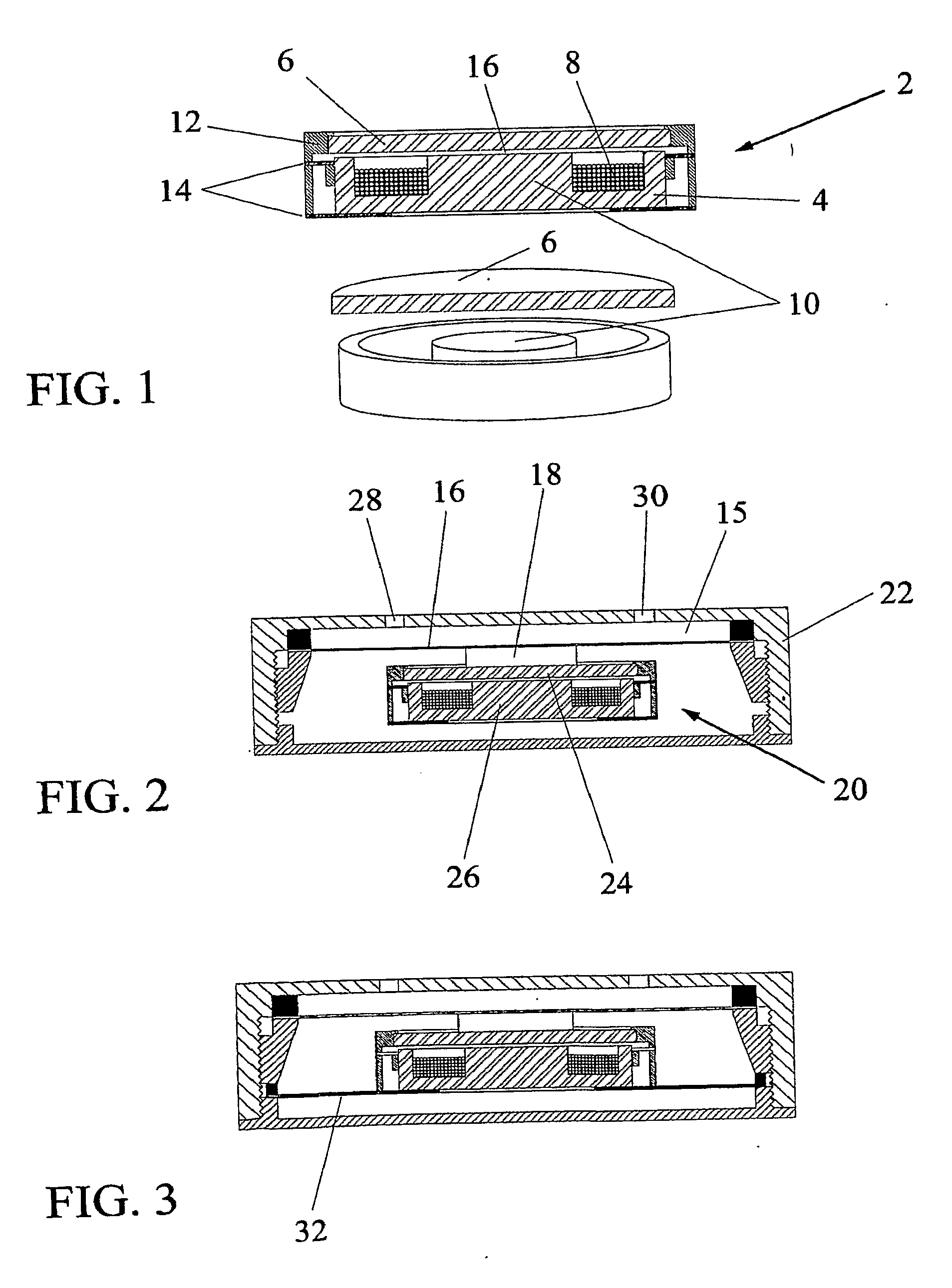
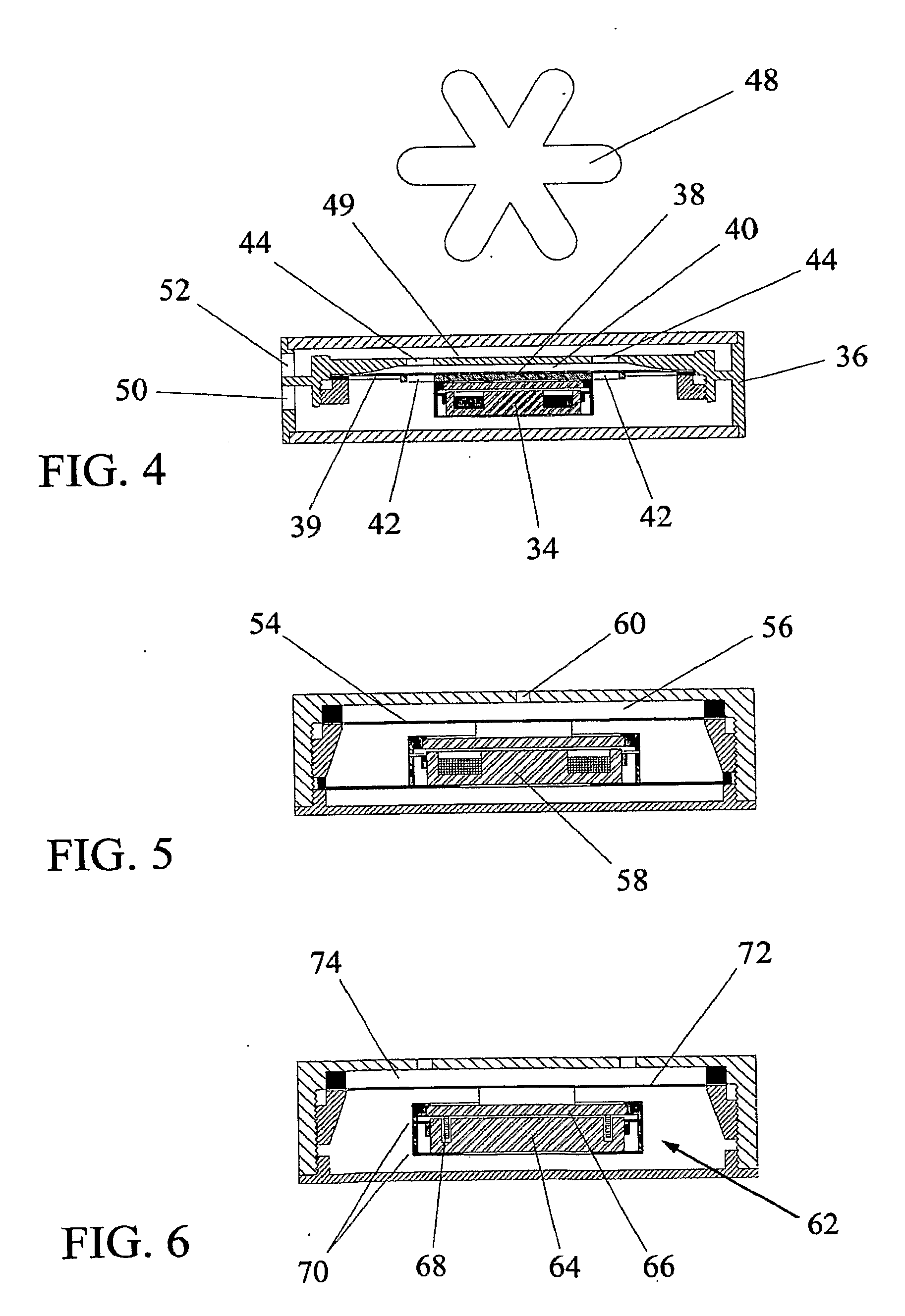
[0162]PCT patent application PCT / US2005 / 046557 describes reaction-drive devices with floating bender actuators (such as piezoceramics or any number of other electro-active actuators) the contents of which are incorporated herein by reference in their entirety. The floating-actuator dynamics of reaction-drive systems enables the use of high-force low-stroke actuators, thereby eliminating the expensive electric motors which drive conventional pumps and compressors. The present invention provides further actuators that can be used in reaction-...


PUM


Abstract

A fluid energy transfer device, including a chamber for receiving a fluid, at least a portion of the chamber comprising a movable portion relative to another portion of the chamber, the movable portion being adapted to change the volume of the chamber from a first volume to a second volume by movement of the movable portion. The device further includes an actuator attached to the movable portion, wherein the displacements of the movable portion can be larger than the displacement of the actuator.

Description

CROSS-REFERENCE TO RELATED PATENT APPLICATIONS[0001]This application claims priority to U.S. Provisional Patent Application No. 60 / 780,037, filed on Mar. 7, 2006, by Timothy S. Lucas of Providence Forge, Va., U.S.A., entitled “Fluidic Energy Transfer Devices,” the contents of which is incorporated herein by reference in their entirety.[0002]The PCT Patent Application PCT / US2005 / 046557, filed Dec. 22, 2005, entitled Reaction-Drive Energy Transfer Device, by Timothy S. Lucas, is hereby referenced, the contents of which are incorporated herein by reference in their entirety.BACKGROUND OF THE INVENTION[0003]1) Field of Invention[0004]This invention relates generally to apparatus and methods for conveying energy into a volume of fluid and more specifically to the field of linear pumps, linear compressors, synthetic jets, resonant acoustic systems and other fluidic devices.[0005]2) Description of Related Art[0006]For the purpose of conveying energy to fluids within a defined enclosure, pr...

Claims


Application Information

Patent Timeline
11 Jun 2009
Publication
US20090148320A1
IPC
F04C21/00; F01B19/00
CPC
F04B43/046
Inventors
LUCAS, TIMOTHY S.