Electro-hydraulic engine valve actuation

a technology of electric hydropower and engine valve, which is applied in the direction of valve arrangement, non-mechanical valve, machines/engines, etc., can solve the problems of not being able to provide a fully flexible valve control system, not being able to provide variable lift control over the full range of valve lift, presently known, etc., to improve system controllability and energy consumption, increase chamber volume, and increase chamber volume

Active Publication Date: 2006-11-16
GM GLOBAL TECH OPERATIONS LLC
View PDF3 Cites 7 Cited by
  • Summary
  • Abstract
  • Description
  • Claims
  • Application Information

AI Technical Summary

Benefits of technology

[0006] The present invention improves system controllability and energy consumption. In accordance with the present invention, a hydraulic actuator for an internal combustion engine valve is presented. The actuator includes a fluidic actuation chamber, defined in part by an actuation piston and characterized by increasing chamber volume as the actuation piston is urged away from a neutral position. The chamber includes a high pressure fluid inlet and a fluid outlet. There is a fluidic actuator control chamber, defined in part by a control piston operably connected to the actuation piston, and characterized by increasing chamber volume as the actuation piston is urged away from the neutral position. The actuator control chamber includes a control fluid outlet. There is a fluid control valve, comprising a spool valve having a fluidic control chamber fluidly connected to the control fluid outlet of the actuator control chamber. The fluid outlet of the actuation chamber is fluidly connected to an inlet of the control valve. There is a valve actuation plunger operably connected to the actuation piston.

Problems solved by technology

While a certain level of flexibility is achievable with cam-based valve actuation systems, e.g., systems employing camshaft phasers, multi-profile cams or lifter deactivation devices, these systems are not able to provide a fully flexible valve control system having a broad range of authority to control valve opening time, duration, and magnitude of lift from fully closed to fully open.
Such systems are camless, but have not been shown to provide variable lift control over full range of valve lift, from fully open to fully closed.
Presently known electro-hydraulic valvetrain systems are undesirably large and costly.
Furthermore, energy consumption and controllability continue to present challenges to production implementation of such systems.

Method used


Image

  • Electro-hydraulic engine valve actuation
  • Electro-hydraulic engine valve actuation

Examples


Embodiment Construction

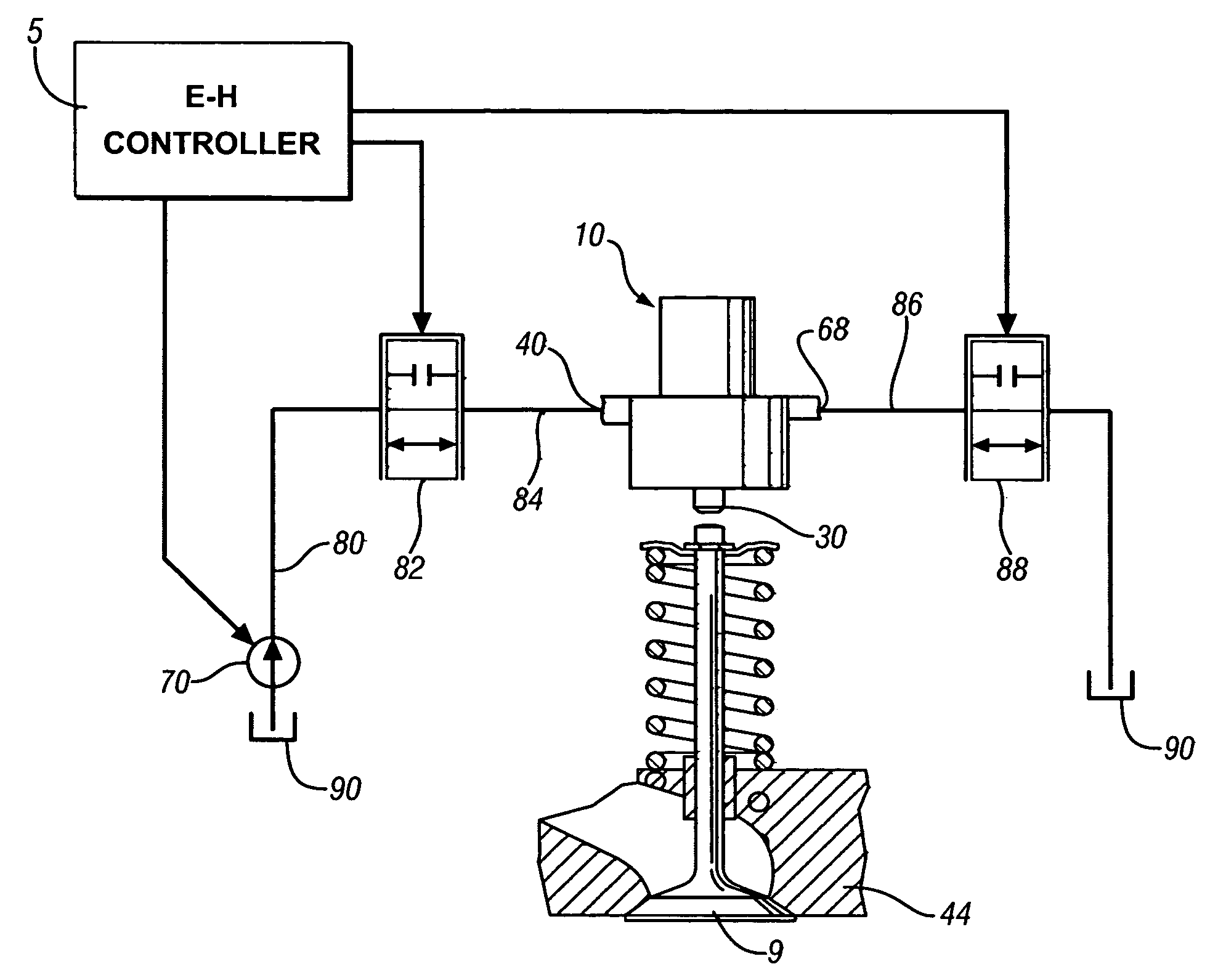
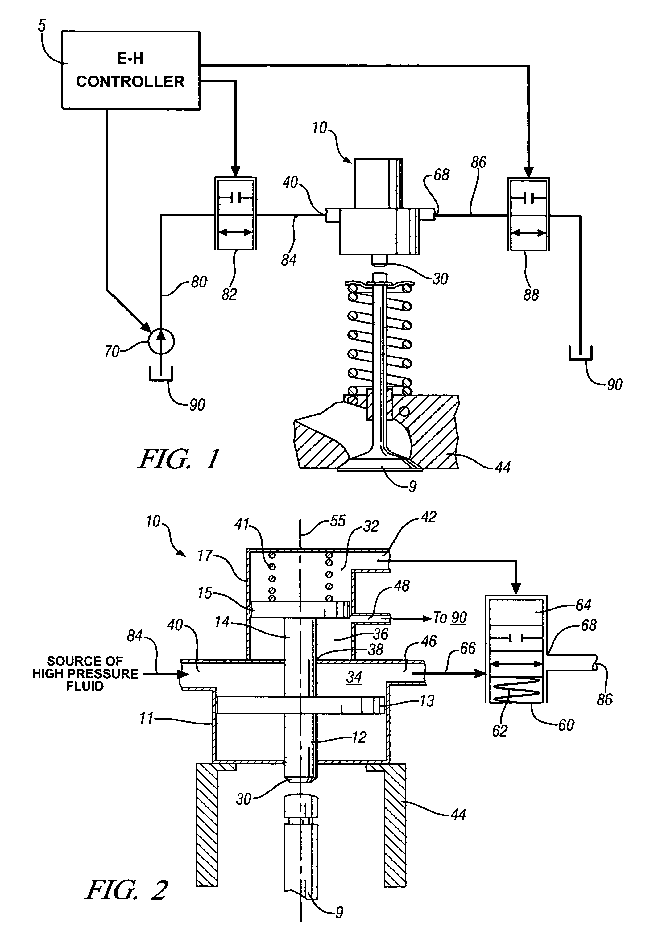
[0017] An exemplary hydraulic engine valve actuator 10 and valve actuation circuit is described hereinbelow, and is intended for application with a fully flexible electro-hydraulic valve actuation system being implemented on a conventionally-constructed constructed multi-cylinder internal combustion engine. The exemplary engine comprises an engine block, a cylinder head 44, a crankshaft, and has a plurality of cylinders formed in the engine block. Each cylinder contains a piston operable to move linearly therewithin, and mechanically operably connected to the crankshaft via a piston rod. The crankshaft is mounted on main bearings attached to the engine block. A combustion chamber is formed in each cylinder between the top of each piston and the cylinder head. The crankshaft rotates in the main bearings, in response to linear force applied thereto by the piston rods, as a result of combustion events in each combustion chamber.

[0018] The cylinder head 44 preferably comprises a conven...


PUM


Abstract

Hydraulic actuator as an element of a system for controlling an engine valve is presented. The actuator includes a fluidic actuation chamber, defined by an actuation piston that increases chamber volume as the actuation piston is urged away from a neutral. Chamber includes a high pressure fluid inlet and a fluid outlet. A fluidic actuator control chamber, defined by a control piston connected to the actuation piston that increases chamber volume as the actuation piston is urged away from neutral. A control fluid outlet is connected to a fluid control spool valve. The fluid outlet of the actuation chamber is fluidly connected to an inlet of the control valve. There is a valve actuation plunger operably connected to the actuation piston, and a drain outlet to maintain a fluidic backpressure to the actuator control chamber.

Description

CROSS-REFERENCE TO RELATED APPLICATIONS [0001] This application claims priority from U.S. Provisional Application No. 60 / 679,322, filed May 10, 2005, entitled ELECTRO-HYDRAULIC ENGINE VALVE ACTUATION.TECHNICAL FIELD [0002] The present invention is related to internal combustion engine valvetrains. More particularly, the invention is concerned with engine valve actuation, especially electro-hydraulically actuated fully flexible valvetrains. BACKGROUND OF THE INVENTION [0003] A valvetrain having fully flexible valve actuation is desirable in an internal combustion engine. The ability to control duration, phase, and lift of each engine valve provides an engine designer with tools to achieve benefits measured in emissions, engine performance and fuel economy not otherwise attainable with conventional valvetrains. While a certain level of flexibility is achievable with cam-based valve actuation systems, e.g., systems employing camshaft phasers, multi-profile cams or lifter deactivation d...

Claims


Application Information

Patent Timeline
Patent Type & Authority Applications(United States)
IPC IPC(8): F01L9/02F01L9/10
CPCF01L9/02F01L9/10
Inventor SUN, ZONGXUAN
Owner GM GLOBAL TECH OPERATIONS LLC
Why Eureka
Try Eureka