
Expandable manifold

Inactive Publication Date: 2007-02-01
EGAN ROBERT M
View PDF8 Cites 3 Cited by
  • Summary
  • Abstract
  • Description
  • Claims
  • Application Information

AI Technical Summary

Benefits of technology

[0007] An exemplary expandable manifold comprises an expansion chamber defined by a resilient surface such as a radiator hose or the like. As reverse impulse flow resulting from the closing of an intake valve enters the expansion chamber, the volume of the chamber increases as the resilient surface expands. The expansion chamber comprises an area (void) toward which the reverse impulse flow tends to propagate and accumulate as the chamber expands. This propagation and accumulation deters the reverse flow from traveling back into and past the carburetor, or source of fuel / air. When the intake valve reopens, the reverse impulse flow is momentarily stored and redirected and combined with intake flow from the source of fuel / air. Accordingly, overall air / fuel intake is increased. This is due, in part to the volume of the chamber decreasing as the resilient surface tends toward its original shape and to the increase in speed / flow of the fuel mixture. Thus, during an increase in pressure within the chamber, when the valve is closed, the reverse impulse flow is essentially prevented from traveling into the fuel / air source. Also, when the valve reopens, the energy associated with the reverse flow is redirected and combined with the forward flow to improve overall engine performance.
[0008] The expandable manifold dynamically adapts to the amount of intake flow and reverse impulse flow. For example, as the throttle of a carburetor is opened, the forward flow increases. When the intake valve closes, the reverse impulse flow correspondingly increases, and the pressure within the expansion chamber also correspondingly increases. As the pressure increases, the resilient surface expands to accommodate the increased pressure. The volume within the chamber also correspondingly increases, thus dynamically accommodating the increased reverse impulse flow. Further the tendency of the resilient surface to “snap back” to its original shape dynamically facilitates the recombination of the redirected reverse impulse flow and the intake flow.

Problems solved by technology

When the intake valve suddenly closes, this forward flow slams to a stop, resulting in high-pressure reverse flow.
During idle, this reverse impulse flow is typically not severe enough to significantly affect engine performance or cause fuel spray through the carburetor.
Detrimental effects of the reverse impulse flow are usually more severe in high performance internal combustion engines (e.g., motorcycle engines).
However, motors of all types, including those utilizing piston porting, conventional valves, reed valves, and also rotary valves used for controlling communication between the intake tract and combustion chamber have a reverse flow problem.

Method used


Image

  • Expandable manifold
  • Expandable manifold
  • Expandable manifold

Examples


Embodiment Construction

[0016] An expandable manifold is described herein with application to internal combustion engines. It is to be understood however, that application of the expandable manifold is not limited to internal combustion engines, but is also applicable to any pneumatically and / or hydraulically operated machine or device. Although described herein in the context of an intake manifold, also it is envisioned that the expandable manifold has application in the exhaust tract of an internal combustion engine or any pneumatically and / or hydraulically operated machine or device.

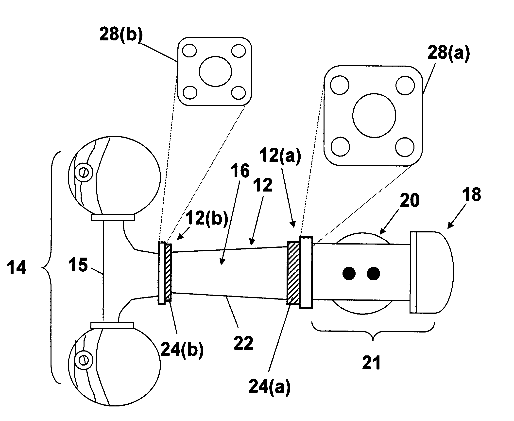
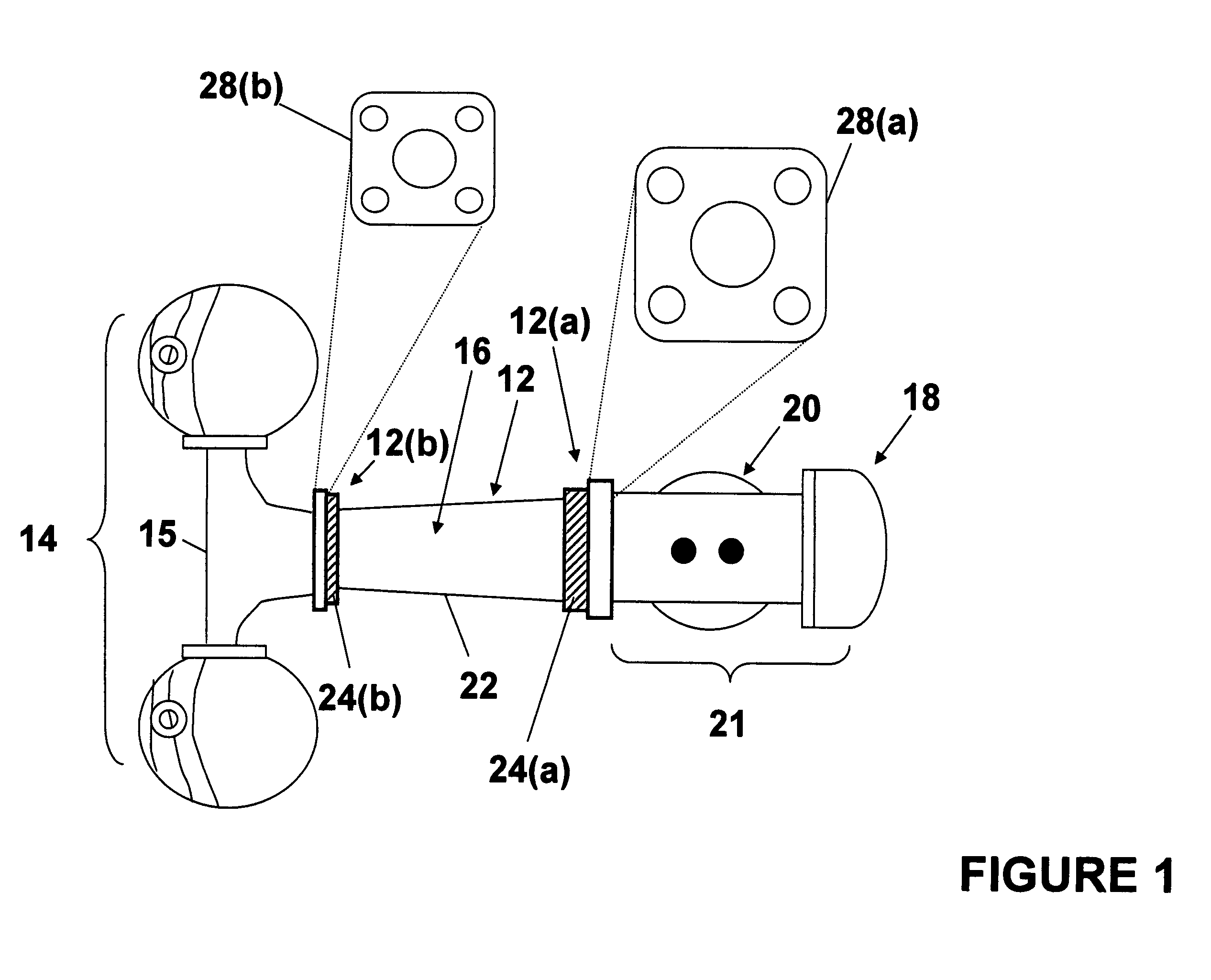
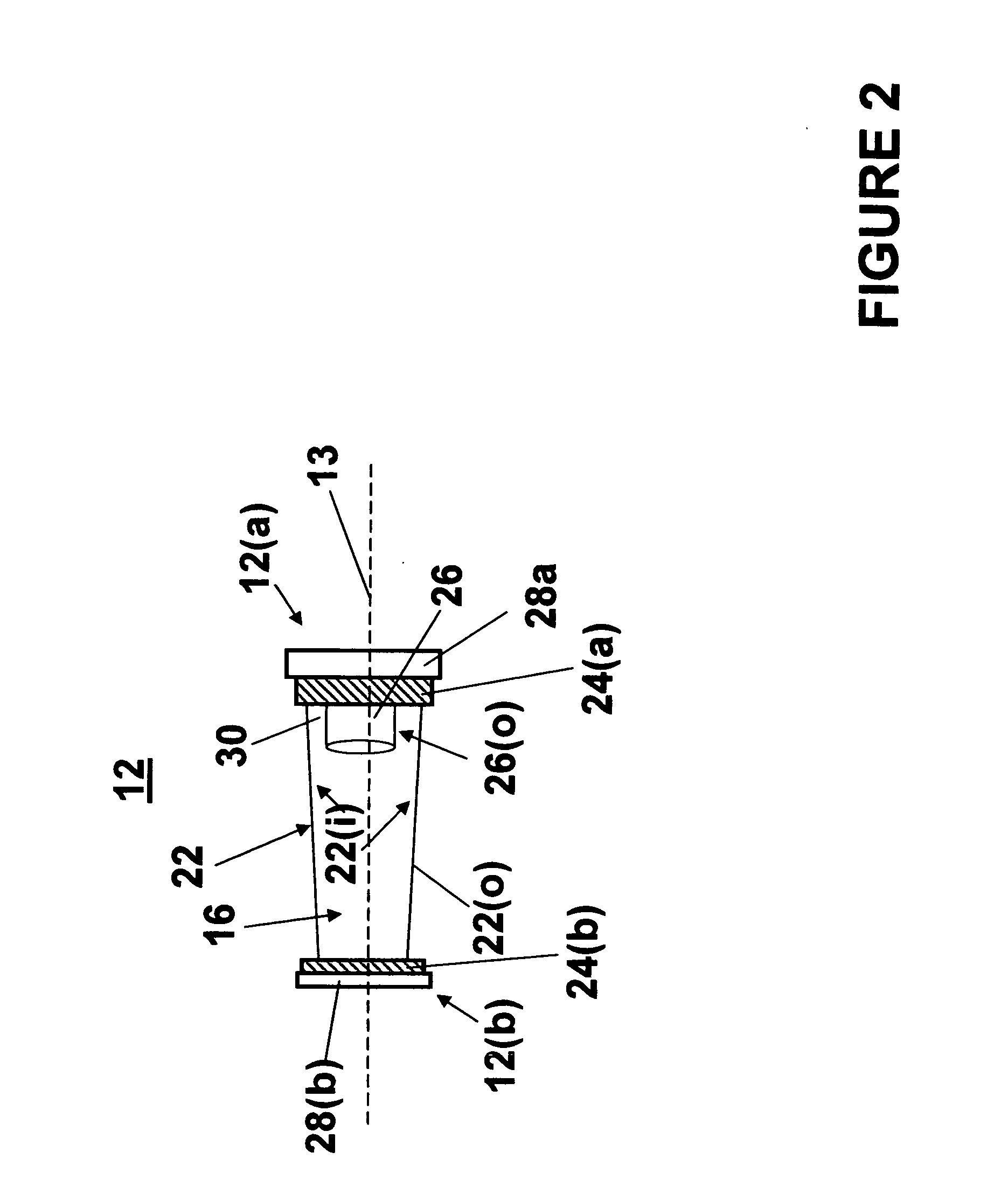
[0017]FIG. 1 is a top view of an expandable manifold 12, functioning as an intake manifold, coupled to cylinder assembly 14 including a manifold 15 and a carburetor assembly 21, in accordance with an exemplary embodiment of the present invention. The carburetor assembly 21 comprises a carburetor 20 and an air cleaner 18. The expandable manifold 12 comprises an intake end 12(a) and an output end 12(b). The intake end 12(a) i...


PUM


Abstract

An expandable manifold comprises an expansion chamber defined by a resilient surface. Intake is provided by a conduit extending into the chamber. As reverse impulses resulting from the closing of an intake valve enter the expansion chamber from the output end of the chamber, the volume of the chamber increases as the resilient surface expands. The reverse impulses propagate along the inner surface of the resilient surface toward a void defined by the outer surface of the conduct and the inner surface of the resilient surface. When the intake valve reopens, the reverse impulse flow is redirected and combined with intake flow from the source of fuel / air. The reverse impulses are redirected within and proximate the void. Energy associated with the reverse flow is redirected and combined with the forward flow to improve overall engine performance.

Description

FIELD OF THE INVENTION [0001] The present invention generally relates to manifolds, and more specifically to a manifold having an expandable portion for utilizing reverse or back pressure within the manifold to improve induction of a gas or fluid within the manifold. BACKGROUND OF THE INVENTION [0002] Intake systems including manifolds for connecting one or more carburetors to a multi-cylinder internal combustion engine are well known. Typically, an air-fuel mixture is provided to the cylinders via the intake manifold. A common goal of many intake systems is to get as much air-fuel mixture into the cylinders as possible. [0003] In a typical intake system, when a cylinder intake valve is open, the air-fuel mixture is pushed by atmospheric pressure into the engine causing the mixture to be rapidly be pushed through the intake manifold toward the combustion chamber. When the intake valve suddenly closes, this forward flow slams to a stop, resulting in high-pressure reverse flow. This h...

Claims


Application Information

Patent Timeline
IPC IPC(8): F02M35/10
CPCF02B27/02F02M35/10118F02M35/10137Y02T10/146F02M35/10275F02M35/162F02M35/10144F02B27/0236F02B27/0247Y02T10/12
Inventor EGAN, ROBERT M.
Owner EGAN ROBERT M
Learn More