Apparatus and method for imaging anterior eye part by optical coherence tomography

an anterior eye part and optical coherence tomography technology, applied in the field of anterior eye part imaging apparatus, can solve the problems of inability to obtain precise 3d image, inferior image quality of obtained tomographic image, and large subject burden, so as to reduce the time period necessary to obtain or take tomographic image, the effect of shortening the time period

Active Publication Date: 2009-06-11
TOMEY CORP
View PDF11 Cites 47 Cited by
  • Summary
  • Abstract
  • Description
  • Claims
  • Application Information

AI Technical Summary

Benefits of technology

The described method allows for easy and accurate correction of tomographic images related to corneal refraction with just one image. It also reduces the amount of time needed to get multiple images. An automatic eye tracking system helps maintain optimal positioning between the cornea and the device while getting the image, ensuring accuracy. Users are able to easily designate areas for imaging through a touch panel.

Problems solved by technology

This patent discusses various ways to improve optical coherence tomographic (OCT) technology for inspecting the eye through tomographic images. One issue addressed is how to quickly get a high-quality 3D image without causing significant strain on the patient and ensuring accurate measurements despite any movements or distortions caused by factors such as refraction on the cornea or changes in position within the eye. Another problem is how to accurately correct errors in the resulting tomographic images due to these same factors.

Method used


Image

  • Apparatus and method for imaging anterior eye part by optical coherence tomography
  • Apparatus and method for imaging anterior eye part by optical coherence tomography
  • Apparatus and method for imaging anterior eye part by optical coherence tomography

Examples


Embodiment Construction

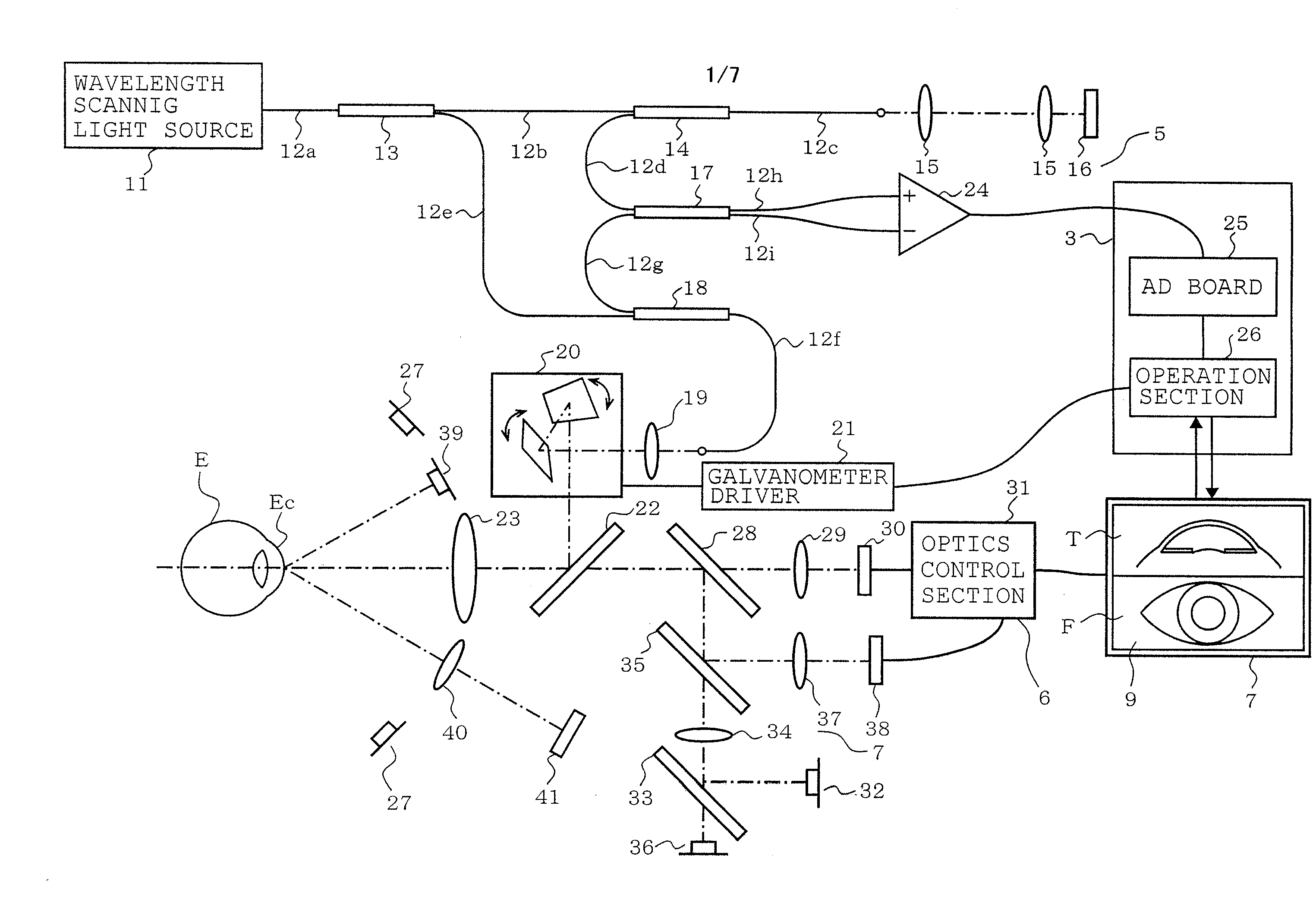
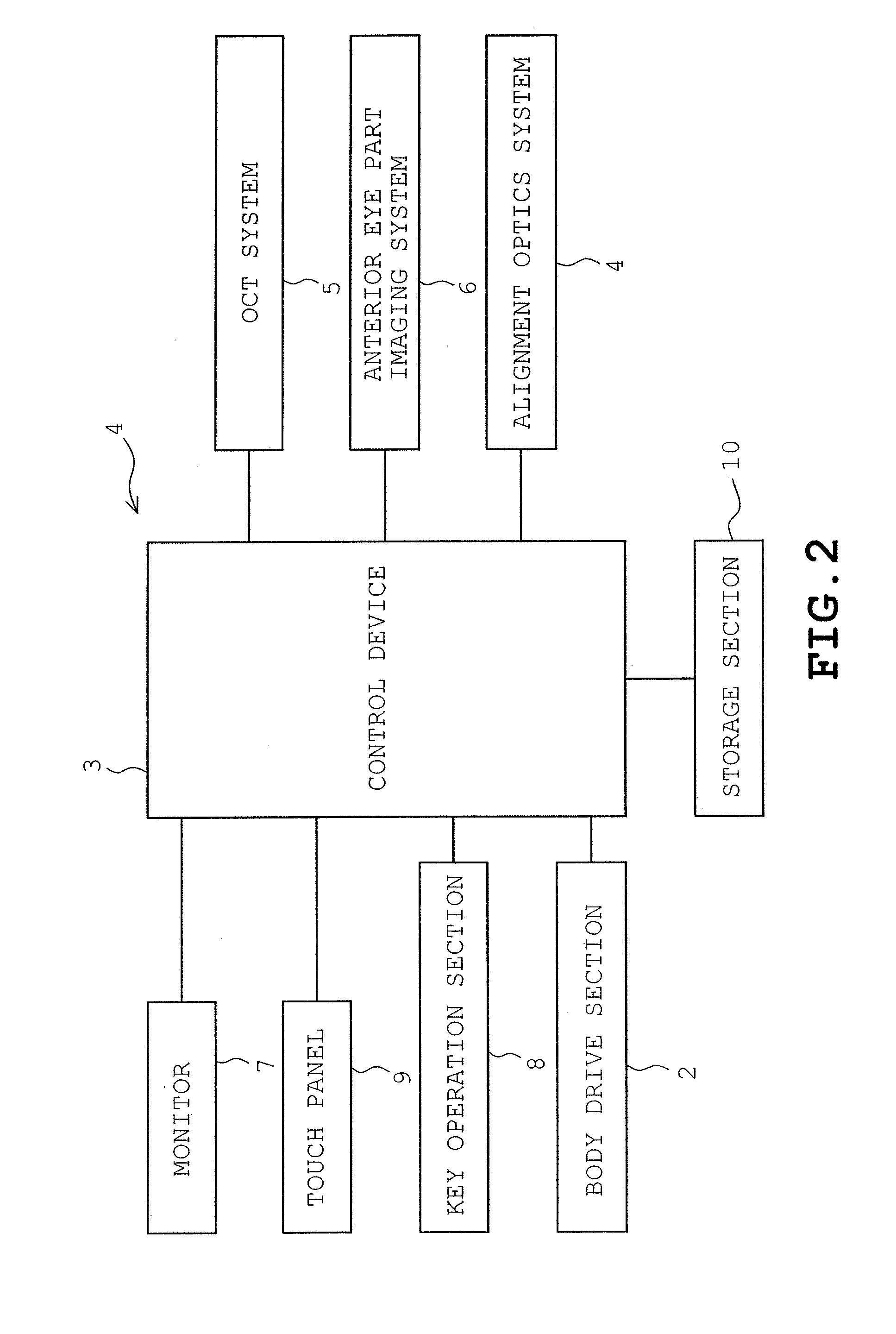
[0032]An embodiment of the present invention will be described with reference to FIGS. 1 to 4 of the accompanying drawings. Referring first to FIG. 2, an electrical arrangement of an optical coherence tomography (OCT) anterior eye part imaging apparatus 1 of the embodiment is shown schematically. The OCT anterior eye part imaging apparatus 1 is used for ophthalmologic examination of an anterior eye part Ec (see FIG. 1) of subjects' eye E such as angle measurement, corneal curvature, corneal thickness distribution or depth of anterior chamber. The OCT anterior eye part imaging apparatus 1 obtains a tomographic image of the anterior eye part Ec of the subject's eye E by an optical coherence tomography method.

[0033]The OCT anterior eye part imaging apparatus 1 includes an apparatus body (not shown) which is mounted on a holder (not shown) so as to be movable in the X-direction (right-and-left direction), the Y-direction (vertical direction) and the Z-direction (front-and-rear direction...


PUM


Abstract

An optical coherence tomography (OCT) anterior eye part imaging apparatus includes a tomographic image obtaining unit obtaining a tomographic image of an anterior eye part of subject's eye in a depth direction by optical coherence tomography, an imaging unit imaging a frontal image of subject's eye, a display unit displaying the image of subject's eye, a corneal apex location detecting unit detecting a location of subject's eye, an alignment unit moving an apparatus body relative to the holder so that the location of corneal apex corresponds with a predetermined image obtaining location, a designating unit designating an area or a location where the tomographic image is obtained on subject's frontal image displayed on the display unit, and a scan line setting unit setting a scan line in the tomographic image obtaining unit on a straight line passing the corneal apex according to the designated area or location.

Description


Claims


Application Information

Patent Timeline
Owner TOMEY CORP
Why Eureka
Try Eureka