Robot

Inactive Publication Date: 2009-06-11
HONDA MOTOR CO LTD
View PDF8 Cites 20 Cited by
  • Summary
  • Abstract
  • Description
  • Claims
  • Application Information

AI Technical Summary

Benefits of technology

[0007]Therefore, an object of the invention is to provide a robot capable of suitably adjusting the position or the like of its body on the current spot from a viewpoint of executing a designated task accompanied by the interaction with a target object.

Problems solved by technology

However, in the second-mentioned method, the position or the like of the first connector may become inappropriate from a viewpoint of connection with the second connector because of the fact that the position, posture, or position and posture (hereinafter properly referred to as “position or the like”) of the second connector undesirably deviates from its inherent or original position and the like, or for the reason that there are inconvenient factors, such as inclination of a floor, or existence of irregularities in a floor on which the robot is positioned even though the robot stops with a designated posture in a designated position (or the robot per se recognizes that it stops with a designated posture in a designated position).
In this case, even if the robot is once moved to another position and is thereafter moved back to a designated position thereof, and has stopped with a designated posture in this designated position, the position or the like of the first connector may still remain unsuitable from a viewpoint of connection with the second connector.
Additionally, when this moving distance becomes long, it is not preferable from a viewpoint of saving of consumption in energy of the robot.

Method used


Image

  • Robot
  • Robot
  • Robot

Examples


Embodiment Construction

[0044]An embodiment of a robot of the present invention will be described hereinbelow with reference to the accompanying drawings. First of all, the general construction of the robot will be described.

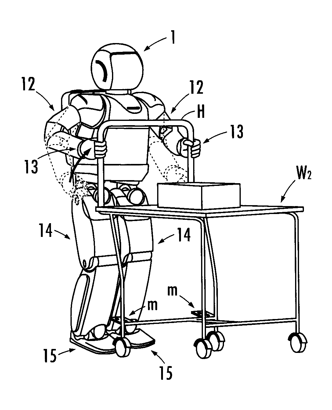
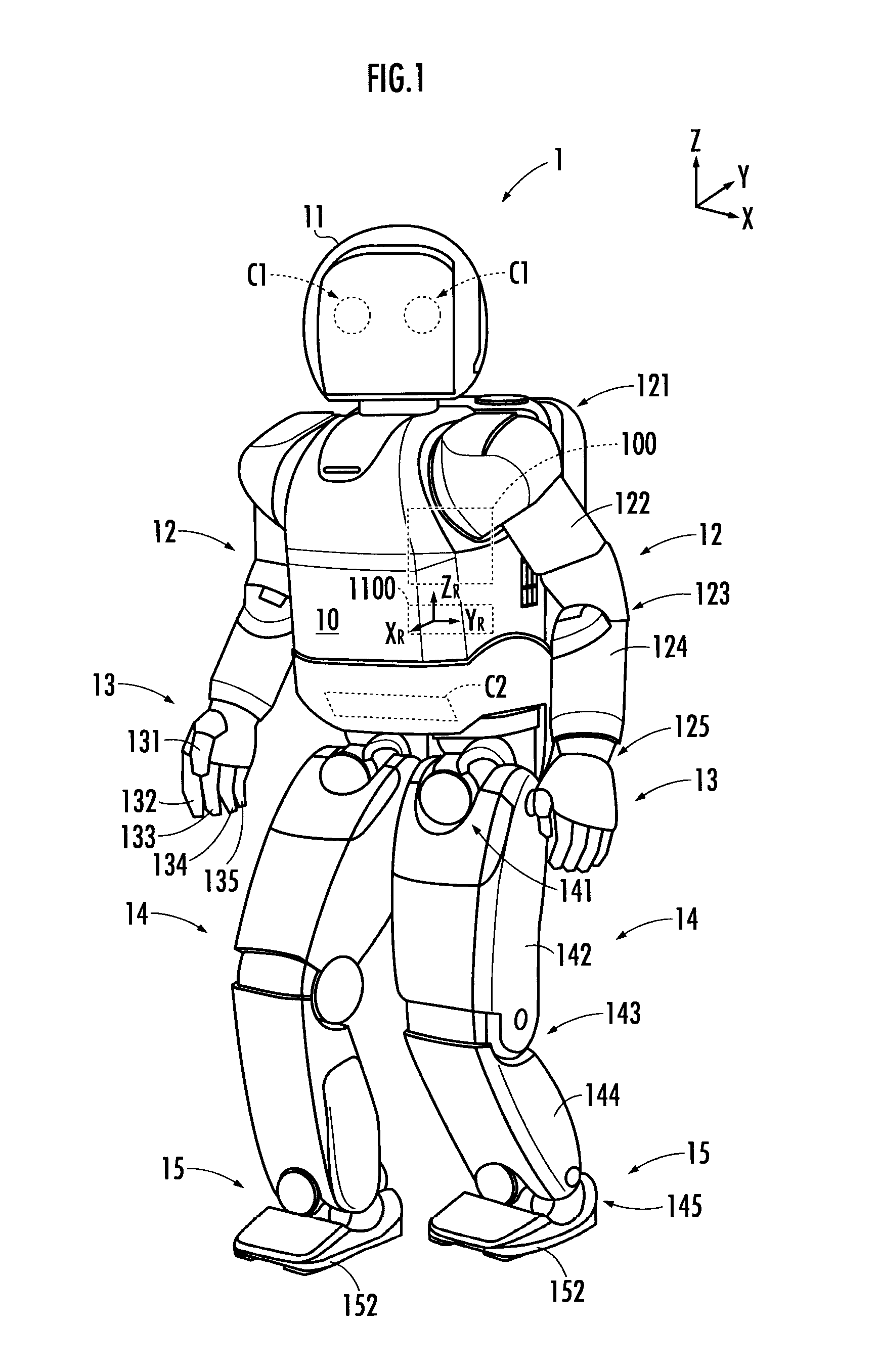
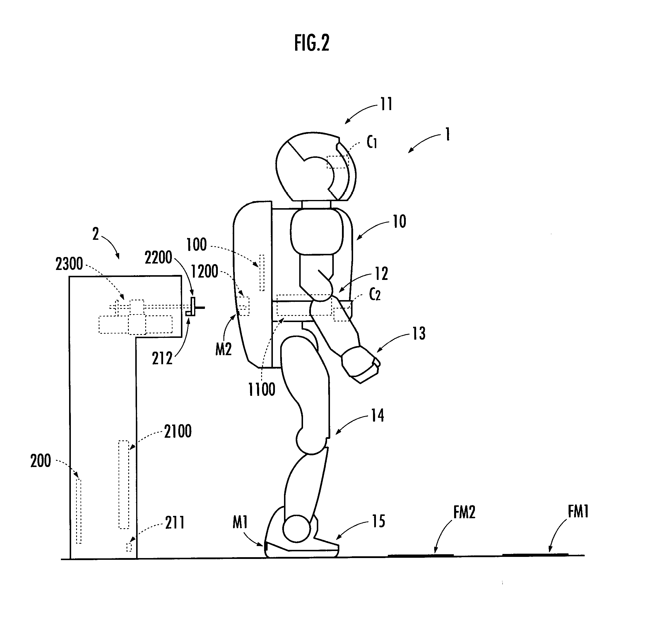
[0045]A robot 1 shown in FIG. 1 is a legged type mobile robot, and like a human being, includes a body 10, a head 11 arranged above the body 10, right and left arms 12 provided at an upper portion of the body 10 to extend from both upper sides, hands 13 provided respectively at the tips of the right and left arms 12, and right and left legs 14 provided to extend downward from a lower portion of the body 10. The robot 1 has a controller 100 which controls the operation thereof, and a battery 1100.

[0046]The body 10 is constituted by an upper portion and a lower portion which are mutually interconnected up and down so as to relatively rotate about a yaw axis. The head 11 can be moved to conduct a rotation about the yaw axis and so on with respect to the body 10. The head 11 is loaded with...


PUM


Abstract

A robot, capable of appropriately adjusting position and / or posture on a current spot to execute a designated task involving interaction with a target object.The Robot is configured to enable adjustment of the position and / or posture by controlling movement of at least a hip joint mechanism, and a knee joint mechanism in the spot while the robot is allowing each foot to keep its floor-arriving state. Accordingly, when the position and / or posture is inappropriate to execute the designated task while the robot is at a standstill in a second designated area for executing the designated task, the robot can execute the designated task after the position and / or posture has been corrected in the second designated area.

Description

BACKGROUND OF THE INVENTION[0001]1. Field of the Invention[0002]The present invention relates to a robot which is capable of autonomously moving by the operation of a plurality of legs extending from a body.[0003]2. Description of the Related Art[0004]There has been proposed a technique for carrying out charging of a battery mounted on an autonomously movable robot (refer to Japanese Patent Application Laid-Open No. 2007-245332). According to this technique, a reliable connection between a first connector provided for a body of the robot and a second connector that is owned by a charging installation is attained by moving the robot so as to be guided by a guide member on the side of a battery charge station.[0005]Meanwhile, as a method of connecting the first connector and the second connector, in addition to the method in which the robot is moved relative to the charging installation, it may be possible to contemplate a method of driving the second connector by a drive provided for...

Claims


Application Information

Patent Timeline
IPC IPC(8): G06F19/00B25J5/00B25J13/00B25J13/08
CPCB62D57/032B25J19/005
Inventor NEKI, NORIOOKAZAKI, KOJINAKAYAMA, TAKASHIMUROMACHI, MASAAKIKANEKO, SATOSHIKIMURA, YUTA
Owner HONDA MOTOR CO LTD
Why Eureka
Try Eureka