Signaling rodent trap system

a technology of rodent traps and signs, which is applied in the field of rodent traps, can solve the problems of user difficulty in checking the state of a trap or a trap, and achieve the effects of simple construction, easy use and inexpensive production

Inactive Publication Date: 2009-06-18
DALEY JAMES D
View PDF6 Cites 33 Cited by
  • Summary
  • Abstract
  • Description
  • Claims
  • Application Information

AI Technical Summary

Benefits of technology

[0002]Conventional devices for trapping rodents, such as mice or rats, are well known. One limitation to such traps is a user must continually check the state of a trap to see if (1) the trap was successful so as to dispose of the rodent; or (2) was unsuccessful but triggered, requiring the user reset the trap. Complicating matters is the general fact that rodent traps are often most successful when they are set to capture rodents in difficult to reach locations such as attics

Problems solved by technology

One limitation to such traps is a user must continually check the state of a trap to see if (1) the trap was successful so as to dispose of the rodent; o

Method used


Image

  • Signaling rodent trap system
  • Signaling rodent trap system
  • Signaling rodent trap system

Examples


first embodiment

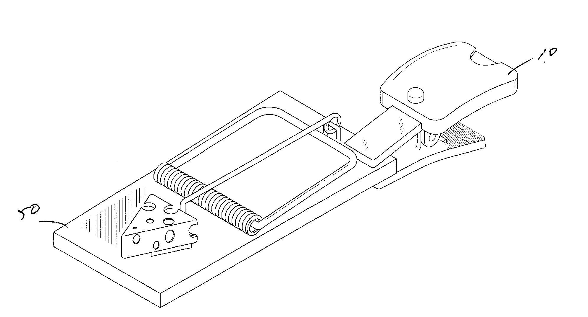
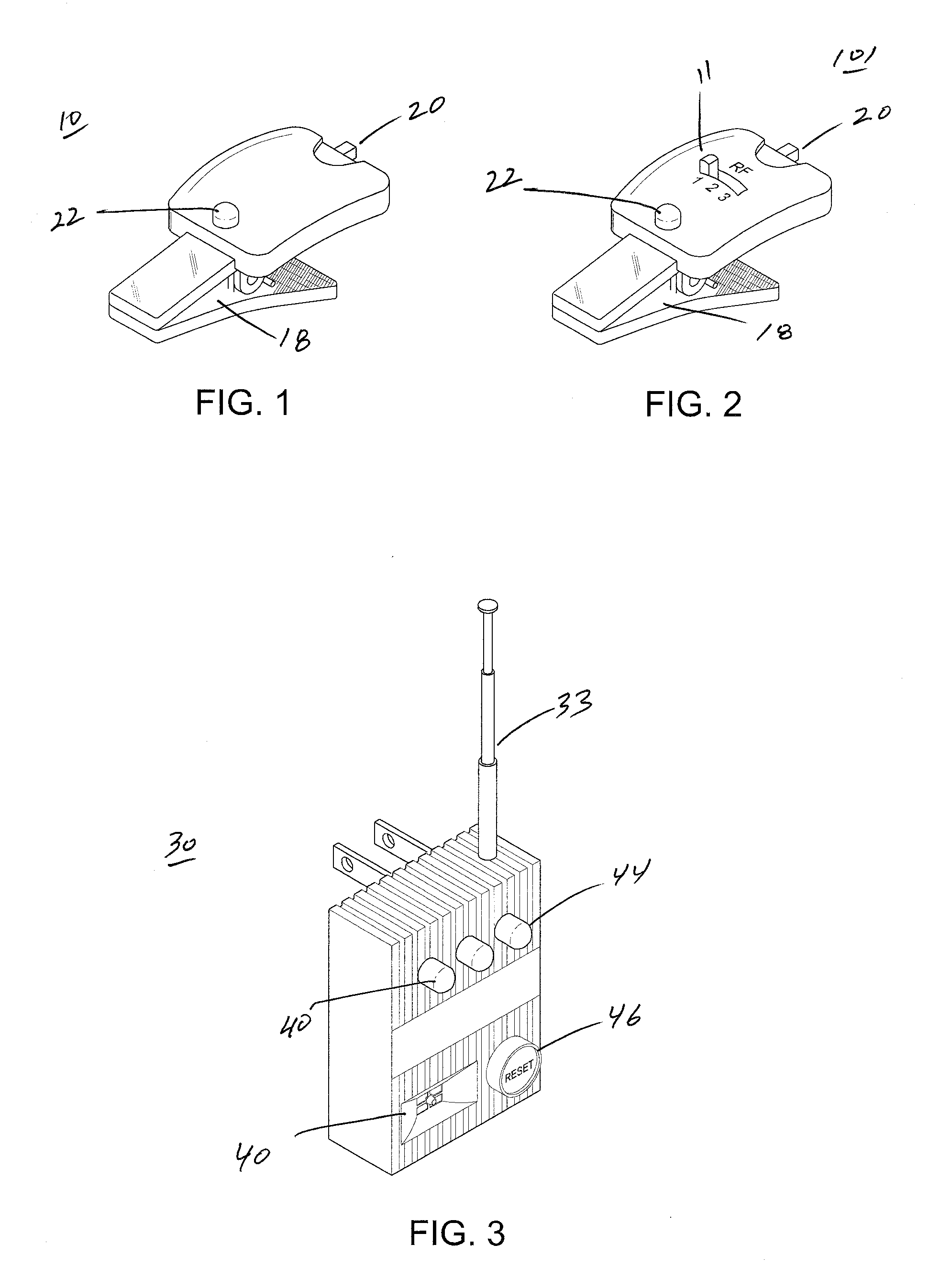
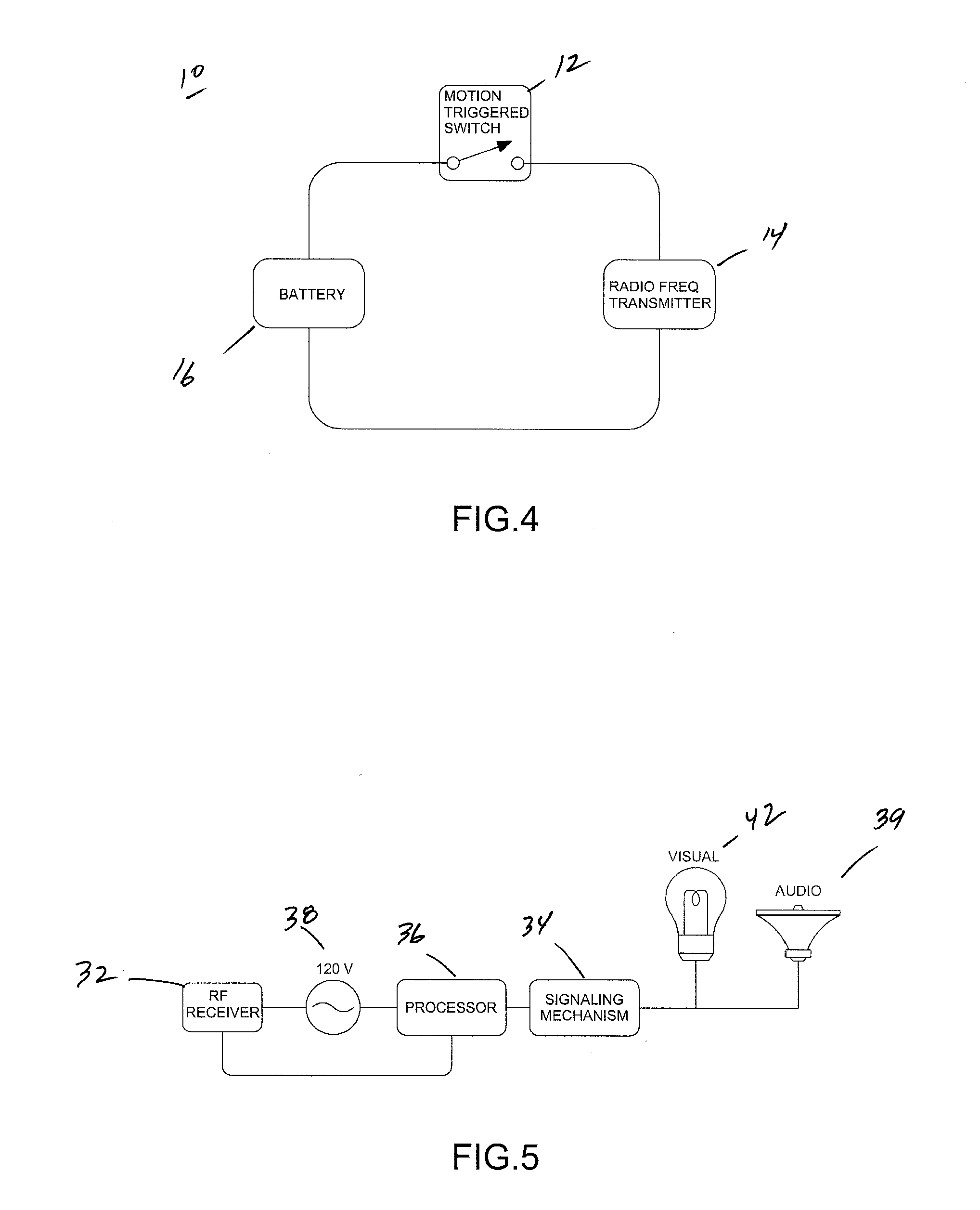
[0019]Referring to FIG. 8, shown therein is a schematic showing the application of the signaling rodent trap system disclosed herein. The system includes a signal transmitting device 10 that is capable of attaching to a rodent trap 50 and a signal receiving device 30. Referring now to FIGS. 1 and 4, shown therein is signal transmitting device 10 and a schematic of the circuitry of that signal transmitting device 10. The signal transmitting device 10 includes a motion triggered switch 12, a rf transmitter 14 electronically connected to said switch for generating a rf signal 13 when the motion trigger switch 12 is activated. The signal transmitting device 10 also includes and a power source such a battery (rechargeable or standard) 16 and means for attaching the signal transmitting device to a rodent trap 50, such as a spring loaded clip 18. An additional attachment means is shown in FIG. 11. As shown in FIG. 4, the battery 16 is only utilized to power the rf transmitter 14 when the m...

second embodiment

[0022]the signaling rodent trap system is shown in FIGS. 2, 6, and 7. In this embodiment, the signal transmitting device 101 is capable generating more than one rf signal, and the signal receiving device 30 is capable of receiving more than one rf signal 13. More specifically, the signal transmitting device 101 includes a rf transmitter switch 11 for selecting between two or more rf signals 13 to be generated by two or more rf transmitters 14. Therefore, in this embodiment, you could have a plurality of signal transmitting devices 101 in different locations each sending a specific rf signal 13 that can be used to determine the location of a given signal transmitting device 101. As described above, in this embodiment as well, the rf signal 13 is transmitted only when the motion trigger switch 12 is activated, thereby conserving battery life. Likewise, the signal receiving device 30 includes a rf receiver 32 that is capable of receiving two or more rf signals 13, a signaling mechanism...


PUM


Abstract

A signaling rodent trap system, the system comprising a signal transmitting device, wherein said signal transmitting device includes a motion triggered switch, a rf transmitter electronically connected to said switch for generating a rf signal only when said motion trigger switch is activated, a power source that is utilized to power said rf transmitter only when said motion triggered switch is activated, and, means for attaching said signal transmitting device to a rodent trap; and, a signal receiving device, wherein said signal receiving device includes a rf receiver for receiving said rf signal from said transmitter, a signaling mechanism for indicating a rf signal has been received by said receiver, a processor electronically connected between said signaling mechanism and said rf receiver for activating said signaling mechanism when a rf signal is received by said receiver, and, a power source for powering said signal receiving device.

Description

BACKGROUND OF INVENTION[0001]This application relates generally to rodent traps. More specifically, this application relates to a signaling rodent trap system that utilizes wireless communication to indicate whether a given rodent trap has sprung.SUMMARY[0002]Conventional devices for trapping rodents, such as mice or rats, are well known. One limitation to such traps is a user must continually check the state of a trap to see if (1) the trap was successful so as to dispose of the rodent; or (2) was unsuccessful but triggered, requiring the user reset the trap. Complicating matters is the general fact that rodent traps are often most successful when they are set to capture rodents in difficult to reach locations such as attics, basements, crawl spaces, cabinets, and behind furniture. As such, this makes it difficult for a user to check the state of a trap or traps. Described herein is a signaling rodent trap system trap system that is easy to use and solves the problems mentioned abo...

Claims


Application Information

Patent Timeline
IPC IPC(8): A01M23/00
CPCA01M23/245
Inventor DALEY, JAMES D.
Owner DALEY JAMES D
Why Eureka
Try Eureka