
Battery unit mounting structure for electric vehicle

a technology for electric vehicles and mounting structures, applied in battery/fuel cell control arrangements, cell components, propulsion by batteries/cells, etc., can solve the problems of increased manufacturing costs, components that require laborious control or management, and the mounting portions of the battery unit cannot share the reinforcing members of a common shape, etc., to achieve the effect of increasing strength

Active Publication Date: 2009-06-18
MITSUBISHI MOTORS CORP
View PDF26 Cites 82 Cited by
  • Summary
  • Abstract
  • Description
  • Claims
  • Application Information

AI Technical Summary

Benefits of technology

[0009]The object of the present invention is to provide a battery unit mounting structure designed so that battery unit mounting portions of side members can be increased in strength and components can be standardized.
[0011]According to this arrangement, the reinforcing member can increase the strength of a battery unit mounting portion of the side member against a load that acts in a transverse direction of the vehicle body. The reinforcing member is provided at a position corresponding to the nut member within the side member. In mounting the reinforcing member in a region where the distance between the sidewalls is different, based on the cross section of the side member, the position of a bent portion of the reinforcing member can be adjusted to fit the distance between the sidewalls of the side member. Thus, in providing the reinforcing members on a plurality of battery unit mounting portions of the side member with different cross sections, components of the reinforcing members can be standardized.

Problems solved by technology

In some cases, therefore, the battery unit mounting portions cannot share reinforcing members of a common shape.
In this case, many types of components must be used, so that the manufacturing cost is increased, and in addition, the components require laborious control or management.

Method used


Image

  • Battery unit mounting structure for electric vehicle
  • Battery unit mounting structure for electric vehicle
  • Battery unit mounting structure for electric vehicle

Examples


Embodiment Construction

[0024]One embodiment of the present invention will now be described with reference to FIGS. 1 to 8.

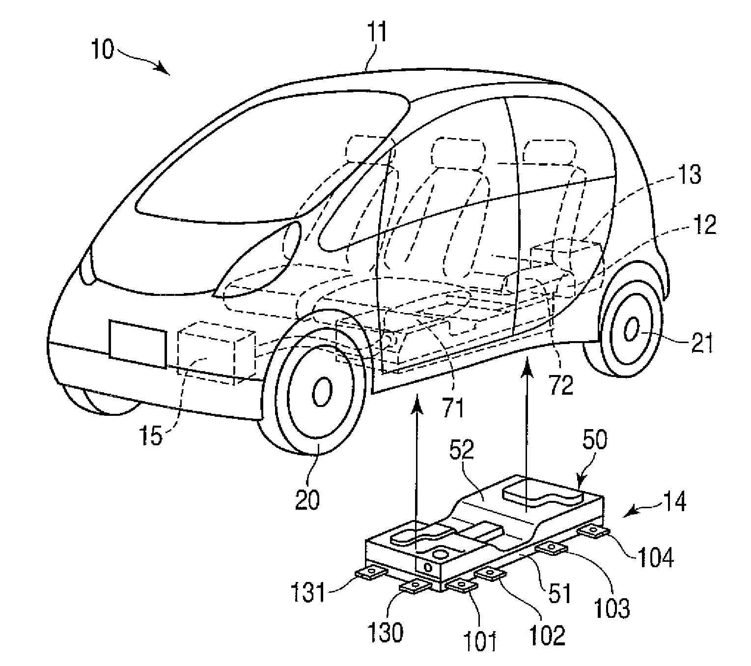
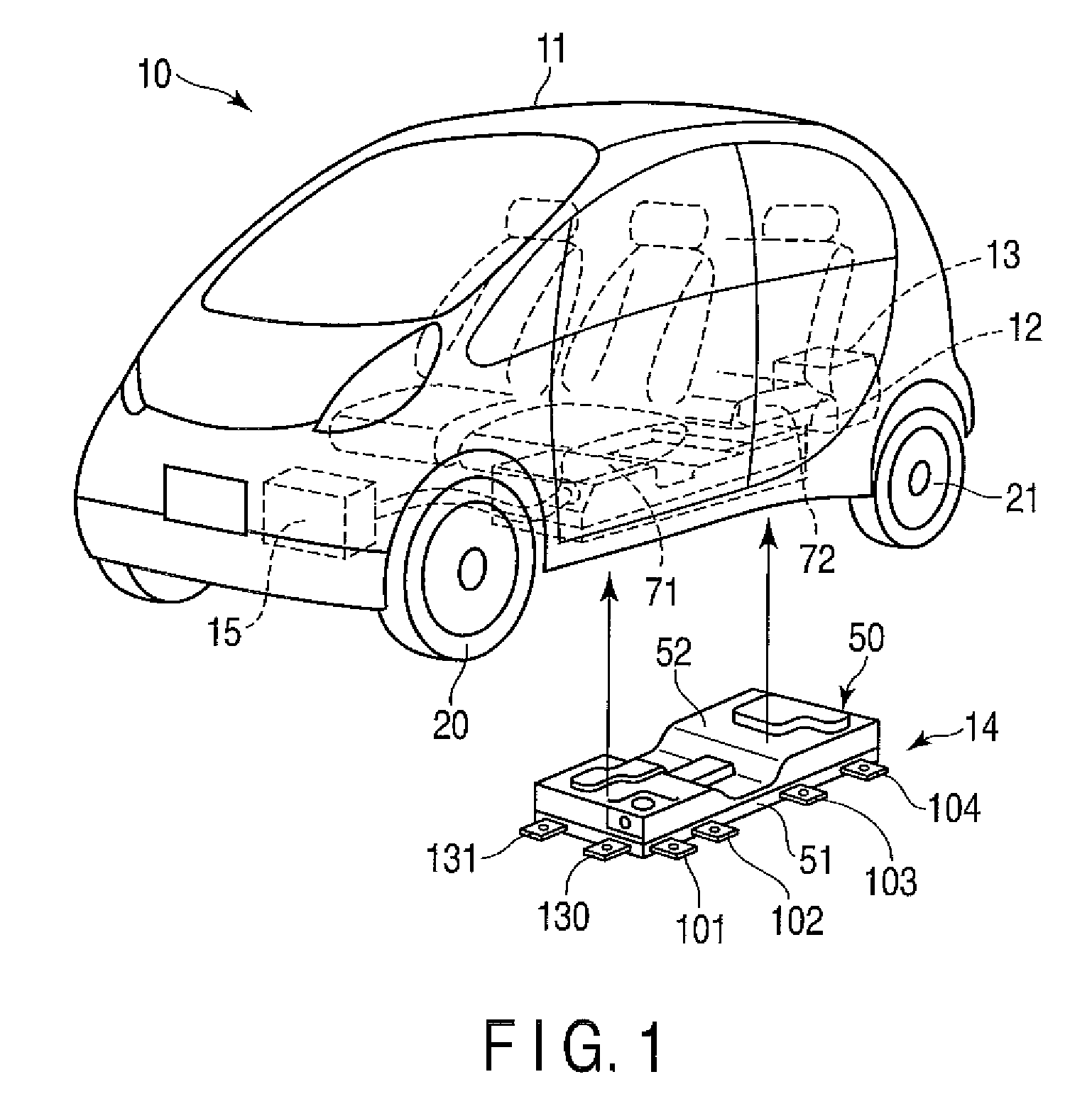
[0025]FIG. 1 shows an example of an electric vehicle 10. The electric vehicle 10 is provided with a traction motor 12 and a charger 13, which are located at the rear part of a vehicle body 11, a battery unit 14 under the floor of the vehicle body 11, etc. A heat exchange unit 15 for cooling and heating is disposed in the front part of the vehicle body 11.

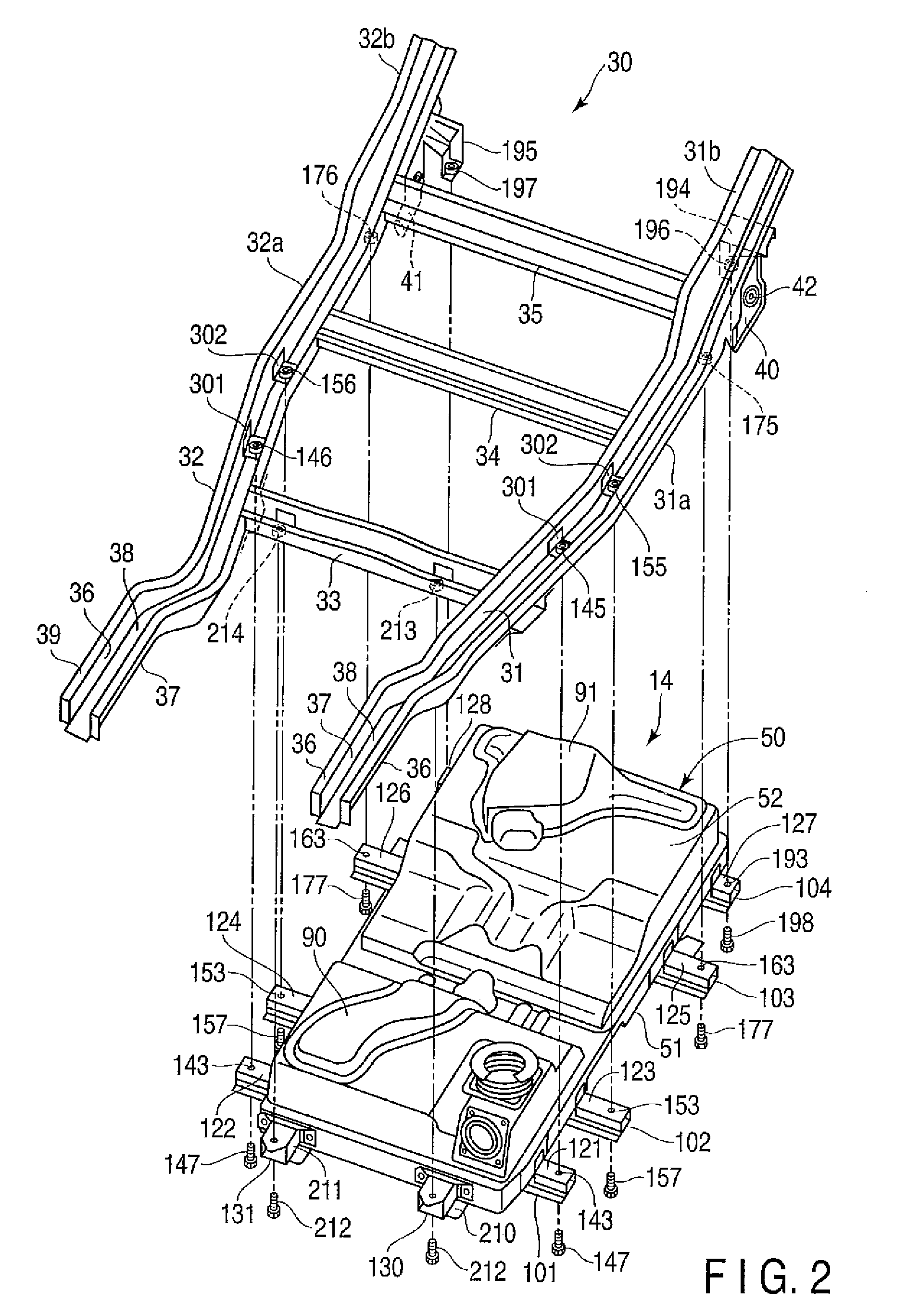
[0026]FIG. 2 shows a frame structure 30, which forms a framework of the lower part of the vehicle body 11, and the battery unit 14 to be mounted on the frame structure 30. The frame structure 30 includes a pair of side members 31 and 32 (left and right), which extend in the longitudinal direction of the vehicle body 11, and cross members 33, 34 and 35 extending in the width direction of the vehicle body 11. The cross members 33, 34 and 35 are fixed in predetermined positions on the side members 31 and 32 by welding.

[0027]The side membe...


PUM


Abstract

A beam member is fixed to a side member of a vehicle body. The side member is provided with a nut member and a reinforcing member. A bolt is inserted into the nut member from under the side member. The reinforcing member includes first and second plate portions. The first plate portion includes a pair of flanges that are bent individually at bent portions. The respective positions of the bent portions are adjusted depending on a distance between sidewalls of the side member. The flanges are welded to the sidewalls. The second plate portion includes a base portion welded to the lower end of the nut member and an upright portion extending along the nut member.

Description

CROSS-REFERENCE TO RELATED APPLICATIONS[0001]This application is based upon and claims the benefit of priority from prior Japanese Patent Application No. 2007-323729, filed Dec. 14, 2007, the entire contents of which are incorporated herein by reference.BACKGROUND OF THE INVENTION[0002]1. Field of the Invention[0003]This invention relates to a battery unit mounting structure for fixing a battery unit as a power source for an electric vehicle to a vehicle body.[0004]2. Description of the Related Art[0005]An electric vehicle is expected to be mounted with a large battery unit to maximize its mileage. Therefore, some battery units may weigh more than, for example, 100 kgw. In order to fix one such heavy battery unit securely to side members of a vehicle body, it is essential to increase the strength of battery unit mounting portions of the side members. The side members are also referred to as side frames.[0006]A battery support structure for fixing a battery unit to side members of a ...

Claims


Application Information

Patent Timeline
Patent Type & Authority Applications(United States)
IPC IPC(8): B60R16/04
CPCB60K1/04B60K2001/0438B62D21/09B62D25/20B62D27/065B60K2001/0472B60L1/003B60L50/52B60L50/64B60L50/66B60L58/26B60L58/27B60L2210/30Y02T10/70Y02T10/72B60Y2200/91
Inventor TAKASAKI, SEIICHISHIMURA, NOBUYUKI
Owner MITSUBISHI MOTORS CORP
Learn More