Disk Brake With Guard Screen

Active Publication Date: 2009-06-18
CONTINENTAL TEVES AG & CO OHG
View PDF4 Cites 15 Cited by
  • Summary
  • Abstract
  • Description
  • Claims
  • Application Information

AI Technical Summary

Benefits of technology

[0006]It is an object of the invention to specify a disk brake which avoids the disadvantages of the prior art and whi

Problems solved by technology

Particularly loose objects on the road surface may cause sensitive impact marks on the individual components of the brake, such

Method used


Image

  • Disk Brake With Guard Screen
  • Disk Brake With Guard Screen
  • Disk Brake With Guard Screen

Examples


Embodiment Construction

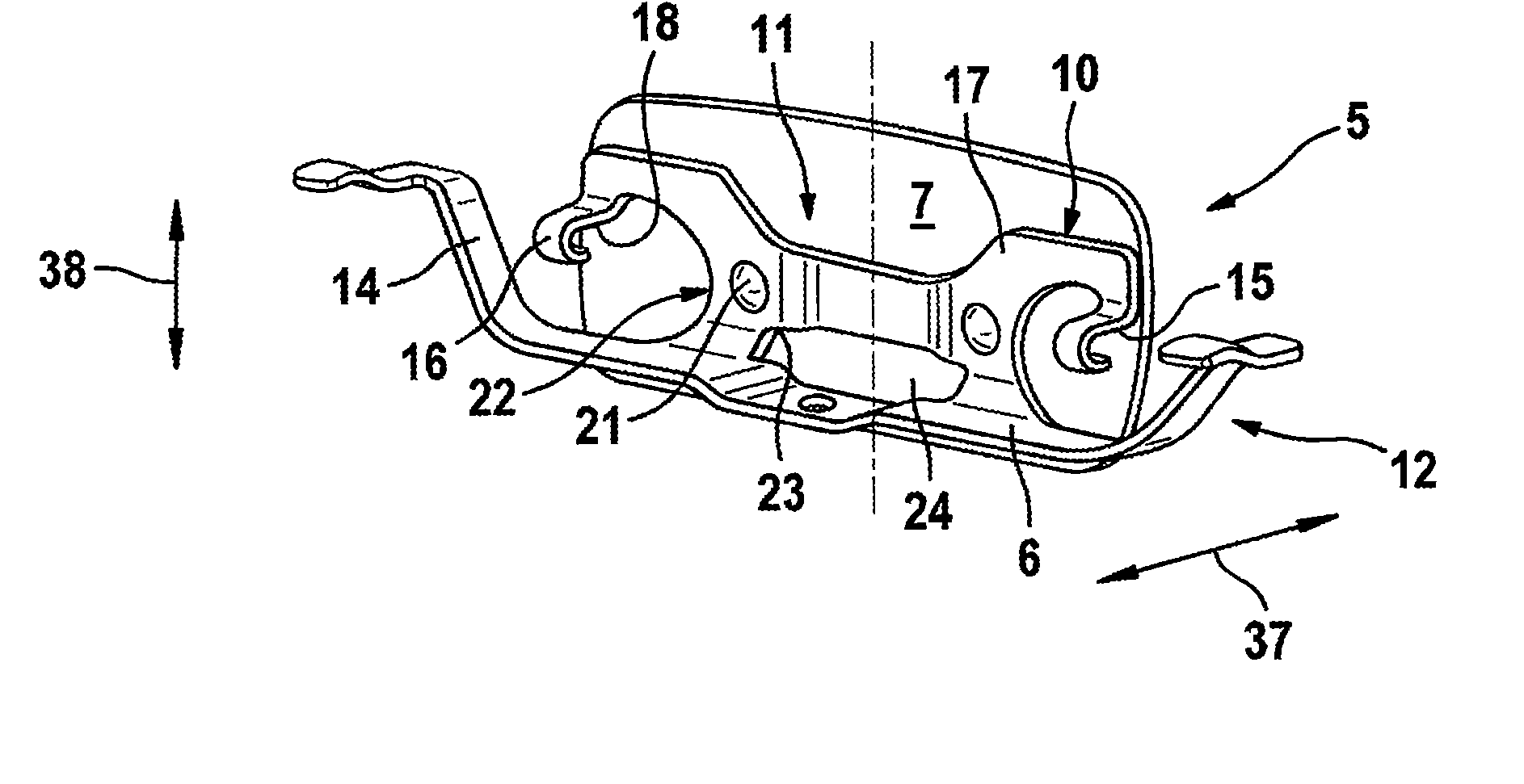
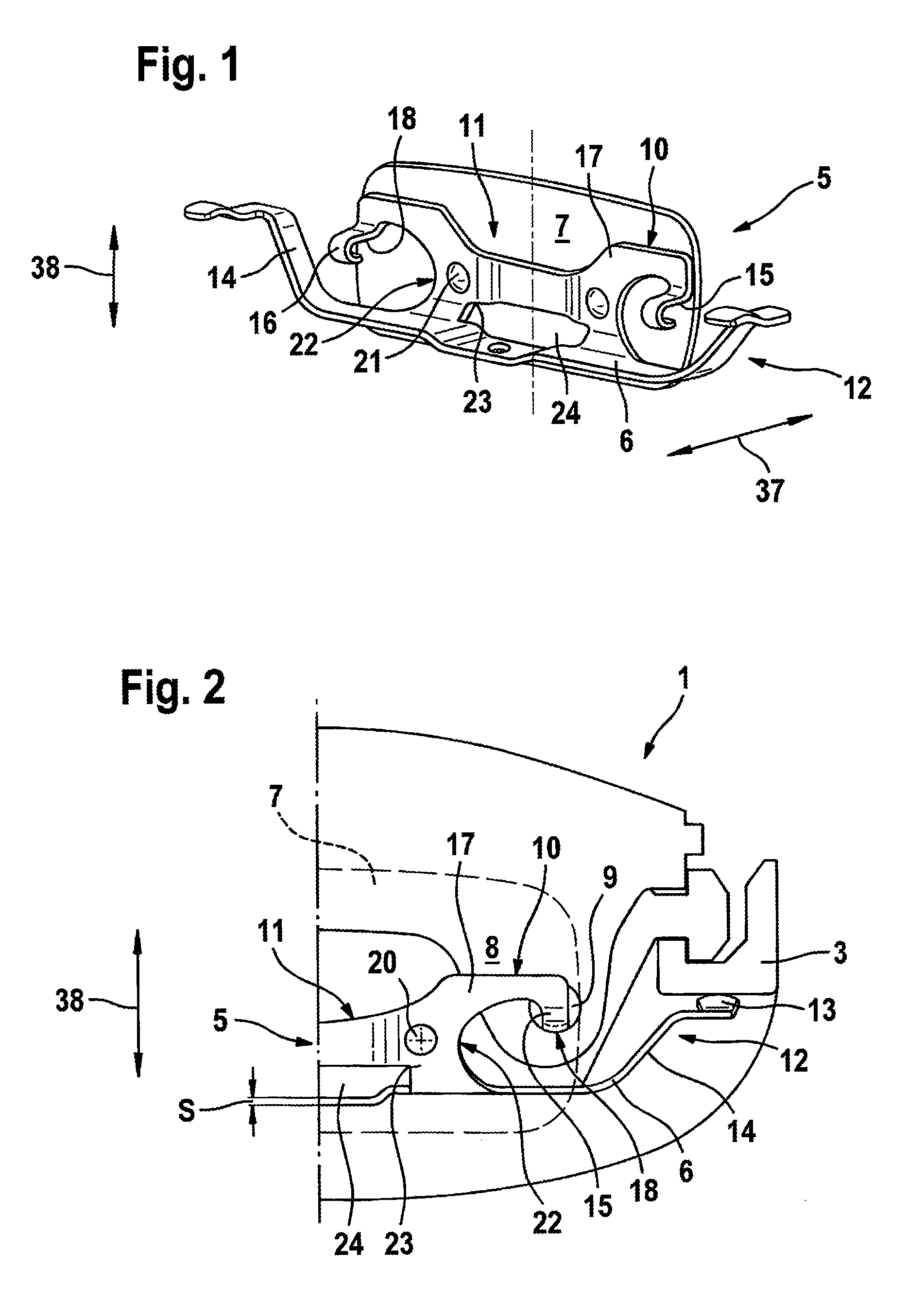
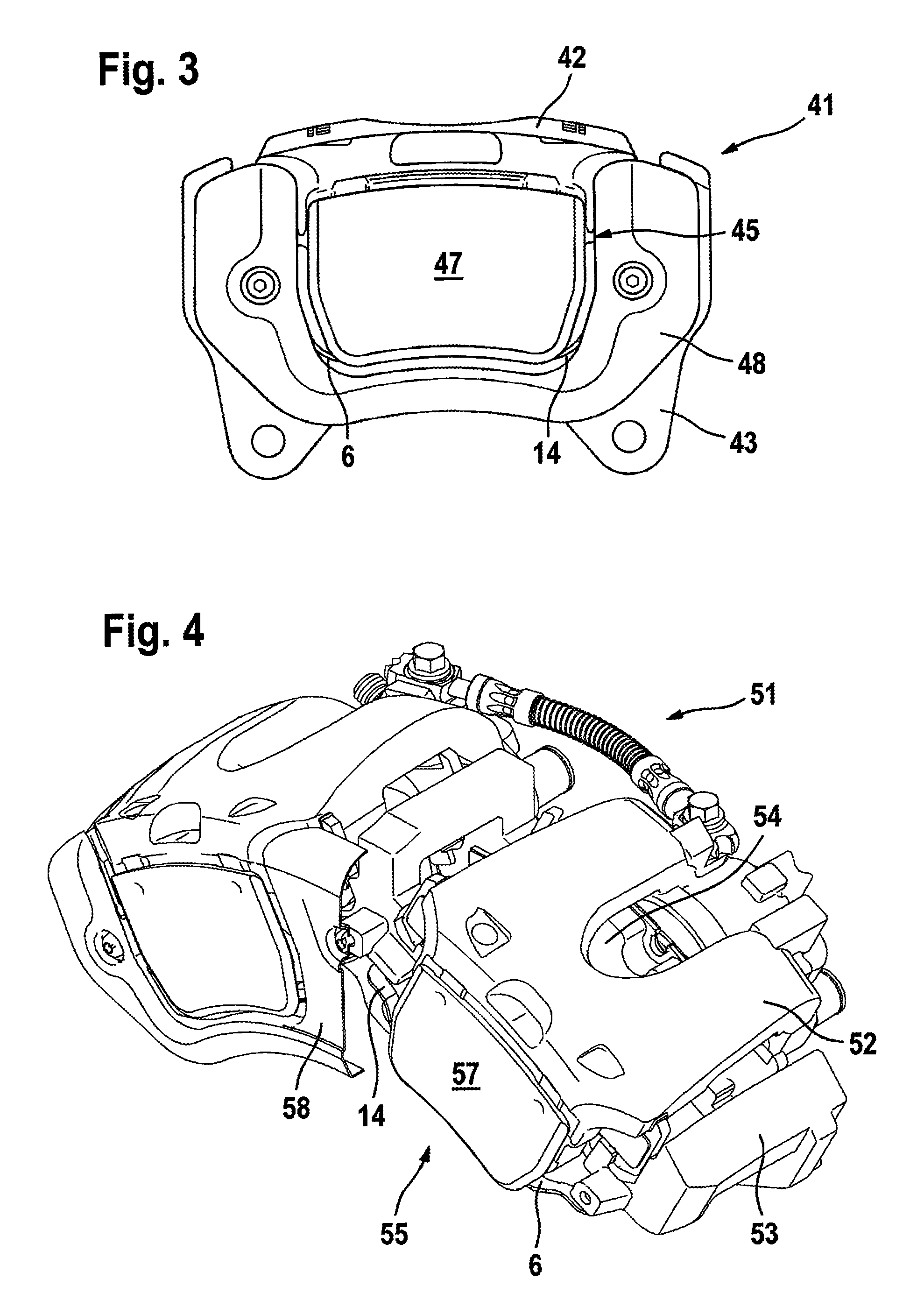
[0033]FIGS. 1 to 4 show a first basic embodiment of a spring arrangement 5,45,55 with a caliper panel 7,47,57, with FIG. 1 illustrating an individual spring arrangement 5 and FIG. 2 to FIG. 4 illustrating the spring arrangement 5,45,55 in the installed state in different disk brakes 1,41,51. The spring arrangement 5 substantially comprises two fastening sections 10, a central section 11 and two spring arms 12. FIG. 2 shows that the spring arms 12 press with in each case a ball-shaped finger 13 against a bracket 3 which is fixed with respect to the vehicle, with in each case one link 14 producing the connection to the central section 11 and substantially generating a preload Fv. The central section 11 merges into the fastening sections 10, which comprise in each case one hook-in device 15 and one support 17. Since the central section 11 and the fastening sections 10 are perpendicular to the spring arms 12, the elastic deformation of the spring arms 12 is a multiple greater than that ...


PUM


Abstract

A disk brake for a vehicle having a bracket which is fixed with respect to the vehicle and on which brake linings and at least one brake caliper are mounted so as to be movable in an axial direction is disclosed. The bracket and the brake caliper engage around at least one brake disk, and the brake caliper includes a housing limb with at least one actuating device, a further housing limb with at least one housing finger, and a housing bridge. A spring arrangement which generates an elastic preload between the brake caliper and the bracket is provided in such a way that the preload is aligned substantially perpendicular to a movement direction of the brake caliper. The spring arrangement comprises a spring element and a protective panel.

Description

CROSS REFERENCE TO RELATED APPLICATIONS[0001]This application is the U.S. national phase application of PCT International Application No. PCT / EP2007 / 054474, filed May 9, 2007, which claims priority to German Patent Application No.: DE102006022699.2, filed May 12, 2006 and German Patent Application No.: DE102006025304.3, filed May 31, 2006, the contents of such applications being incorporated by reference herein in their entirety.BACKGROUND OF THE INVENTION[0002]1. Field of the Invention[0003]The invention relates to a disk brake having a protective panel, having a bracket which is fixed with respect to the vehicle and on which brake linings and at least one brake caliper are mounted so as to be movable in an axial direction, with the bracket and the brake caliper engaging around at least one brake disk, and with the brake caliper having a housing limb with at least one actuating device, a further housing limb with at least one housing finger, and a housing bridge, having a spring ar...

Claims


Application Information

Patent Timeline
IPC IPC(8): F16D55/226F16D65/092
CPCF16D2055/0041F16D65/097F16D55/226F16D65/092
Inventor HEINZ, STEFANSANDER, CHRISTOPHBACH, UWESUNDHEIM, RALFSTOKA, ROBERTO
Owner CONTINENTAL TEVES AG & CO OHG
Why Eureka
Try Eureka