Inner shell for a pressure vessel

a pressure vessel and inner shell technology, applied in the field of hollow vessels, can solve the problems of mechanical failure of the inner shell and useful life, and achieve the effect of reducing the influence of tension forces

Inactive Publication Date: 2009-06-18
GM GLOBAL TECH OPERATIONS LLC
View PDF34 Cites 45 Cited by
  • Summary
  • Abstract
  • Description
  • Claims
  • Application Information

AI Technical Summary

Benefits of technology

[0009]Concordant and congruous with the present invention, a hollow pressure vessel having an outer shell and an inner shell fixed to a boss, the inner shell adapted to minimize the affect of tension forces imparted thereto, has surprising been discovered.

Problems solved by technology

Repeated expansion and contraction of the material, as well as high compressive and tension forces, may result in cracking and mechanical failure of the inner shell, thereby minimizing a useful life of the vessel.

Method used


Image

  • Inner shell for a pressure vessel
  • Inner shell for a pressure vessel
  • Inner shell for a pressure vessel

Examples


Embodiment Construction

[0023]The following detailed description and appended drawings describe and illustrate various exemplary embodiments of the invention. The description and drawings serve to enable one skilled in the art to make and use the invention, and are not intended to limit the scope of the invention in any manner.

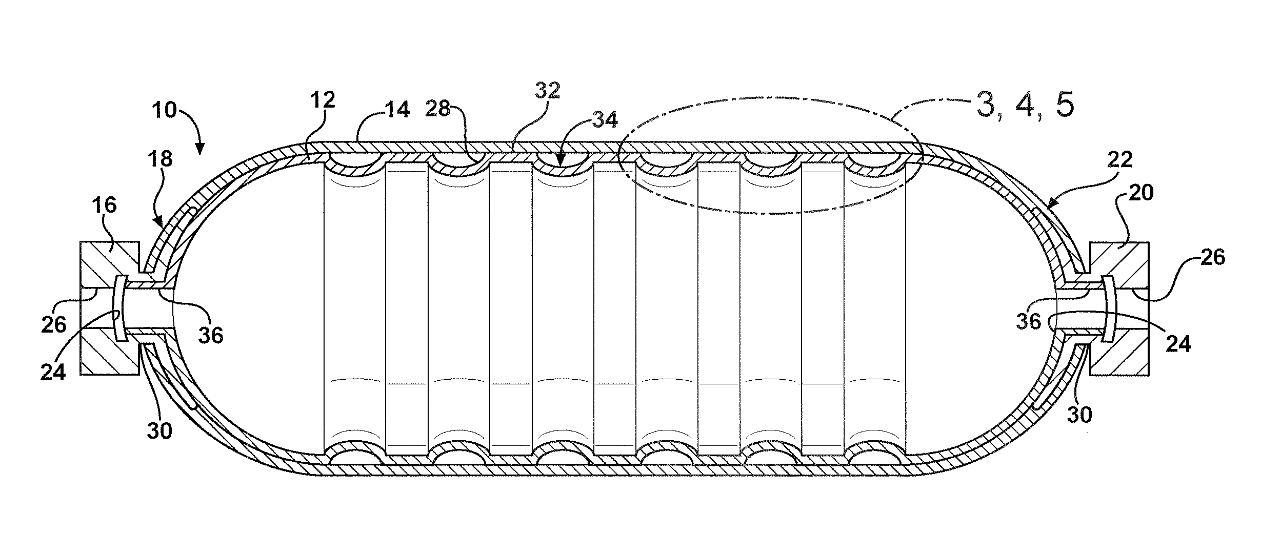
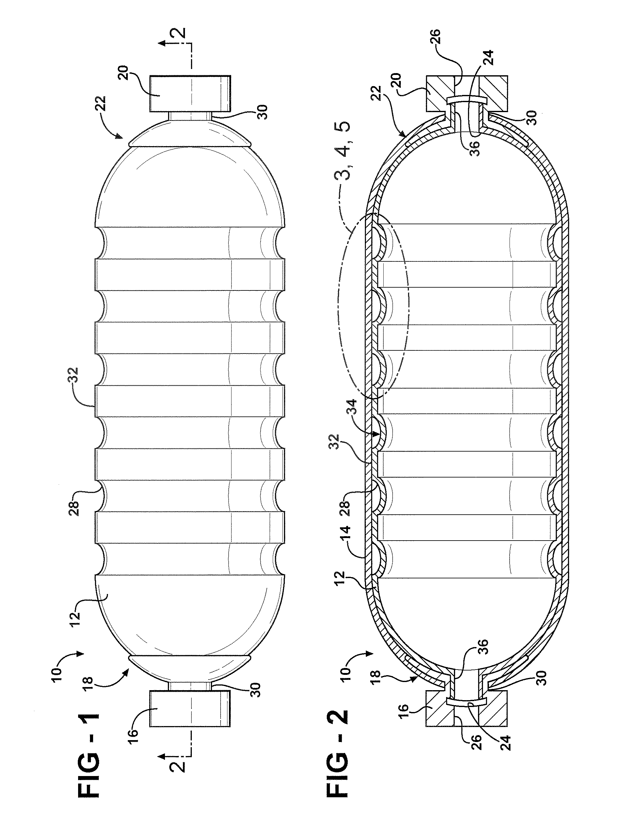
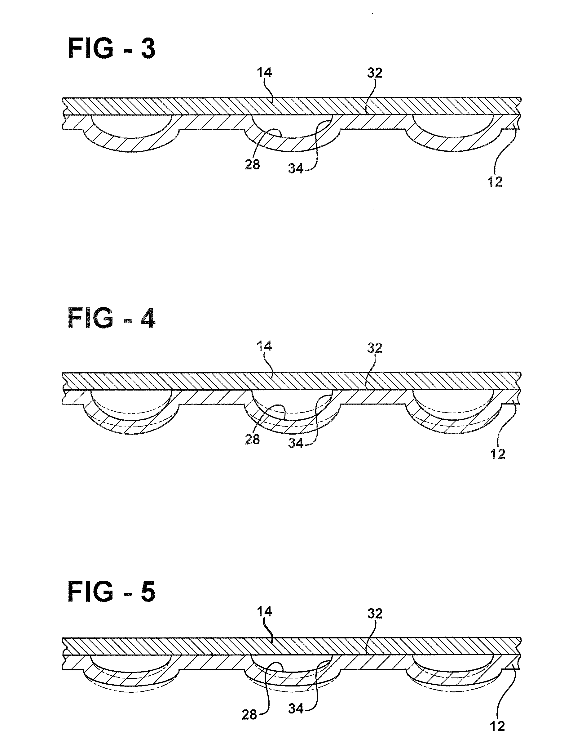
[0024]FIGS. 1 and 2 illustrate a hollow pressure vessel 10 having an inner shell 12 and an outer shell 14. The vessel 10 has a substantially cylindrical shape and is adapted to hold a pressurized fluid (not shown). It is understood that the vessel 10 may have any shape as desired. The pressurized fluid may be any fluid such as a gas, a liquid, and both a liquid and a gas, for example.

[0025]The vessel 10 includes a first boss 16 disposed in a first end 18 thereof and a second boss 20 disposed in a second end 22 thereof. The first boss 16 and the second boss 20 are a separately produced finish that each forms an opening into an interior of the vessel 10. The first boss 16 and the secon...


PUM

PropertyMeasurementUnit
pressuresaaaaaaaaaa
pressuresaaaaaaaaaa
temperatureaaaaaaaaaa

Abstract

Disclosed is a vessel including an outer shell and an inner shell, the inner shell having spaced apart indentations formed therein to facilitate a thermal expansion and contraction of the inner shell to militate against failure thereof.

Description

FIELD OF THE INVENTION[0001]The invention relates to a hollow vessel, and more particularly to a hollow pressure vessel having an outer shell and an inner shell fixed to a boss, the inner shell having an increased surface area over inner shells of pressure vessels known in the art to facilitate an expansion and a contraction thereof and to militate against failure of the inner shell.BACKGROUND OF THE INVENTION[0002]Fuel cells have been proposed as a power source for electric vehicles and other applications. In proton exchange membrane (PEM) type fuel cells, hydrogen is supplied as a fuel to an anode of the fuel cell and oxygen is supplied as an oxidant to a cathode of the fuel cell. A plurality of fuel cells is stacked together in fuel cell stacks to form a fuel cell system. The fuel is typically stored in large, hollow pressure vessels, such as fuel tanks, disposed on an undercarriage of the vehicle.[0003]The pressure vessels are typically multi-layered and include at least an inne...

Claims


Application Information

Patent Timeline
Patent Type & Authority Applications(United States)
IPC IPC(8): F17C1/06
CPCF17C1/00Y02E60/50F17C2201/0123F17C2203/0607F17C2203/0619F17C2203/0621F17C2203/0636F17C2203/0639F17C2203/0646F17C2203/0648F17C2203/0656F17C2203/066F17C2203/0663F17C2203/0685F17C2205/0305F17C2205/0397F17C2209/2118F17C2209/2127F17C2209/2145F17C2209/2181F17C2209/225F17C2223/0123F17C2223/0153F17C2223/033F17C2260/011F17C2270/0184H01M8/04201H01M2008/1095Y02E60/321F17C2201/0109Y02E60/32
Inventor LINDNER, MARKUS
Owner GM GLOBAL TECH OPERATIONS LLC
Why Eureka
Try Eureka