Occupant weight sensor for vehiclular seats, method for making and system therefor

a technology for vehiclular seats and occupants, applied in the field of weight sensors, can solve the problems of airbag deployment being a problem for small children or children, and achieve the effects of reducing the impact of parasitic mechanical loads, reducing the effect of mechanical safety factor, and strong signal-to-noise ratio

Inactive Publication Date: 2005-02-03
SENSATA TECHNOLOGIES INC
View PDF12 Cites 15 Cited by
  • Summary
  • Abstract
  • Description
  • Claims
  • Application Information

AI Technical Summary

Benefits of technology

[0013] According to a feature of the invention, the piezoresistors are composed of monocrystalline silicon which are glass bonded to the sense surface to provide strong signal to noise ratios and high levels of mechanical safety factor. If desired, the piezoresistors of one or more half bridges may be formed on the same piece of silicon.
[0014] According to a modified preferred embodiment, a second full Wheatstone bridge can be provided having piezoresistors disposed 180 degrees from the piezoresistors of the first fill bridge. In this embodiment a summing circuit is connected to the outputs of each full bridge to mitigate affects of parasitic mechanical loads on axially loaded sensors.
[0015] According to a preferred embodiment of the invention, the sense element comprises a first generally cylindrical body having a first longitudinal axis and a portion formed with a circular flat sense surface lying in a plane generally perpendicular to the first longitudinal axis. The body has an outer periphe...

Problems solved by technology

For example, airbag deployment can be a problem for small c...

Method used


Image

  • Occupant weight sensor for vehiclular seats, method for making and system therefor
  • Occupant weight sensor for vehiclular seats, method for making and system therefor
  • Occupant weight sensor for vehiclular seats, method for making and system therefor

Examples


Embodiment Construction

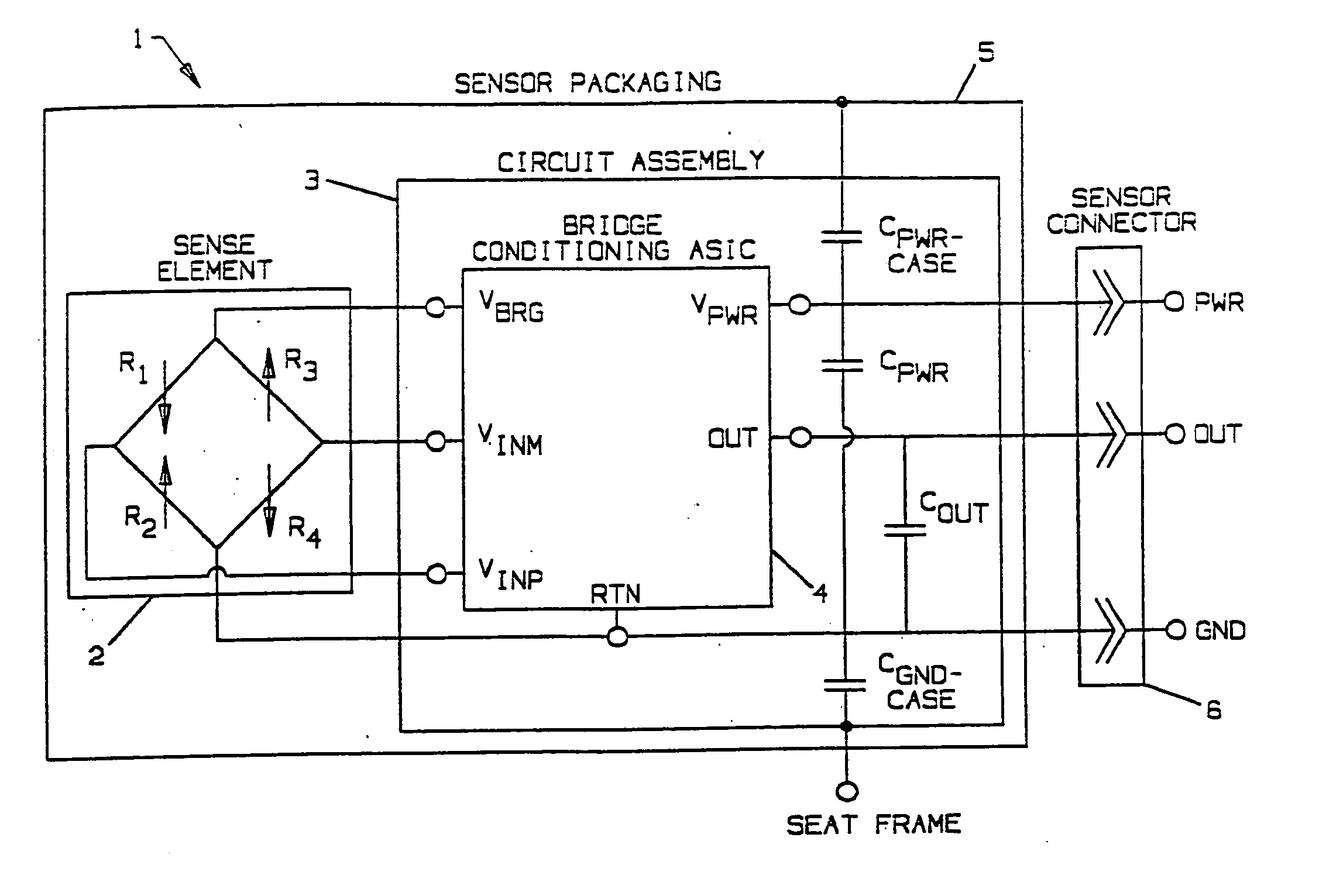
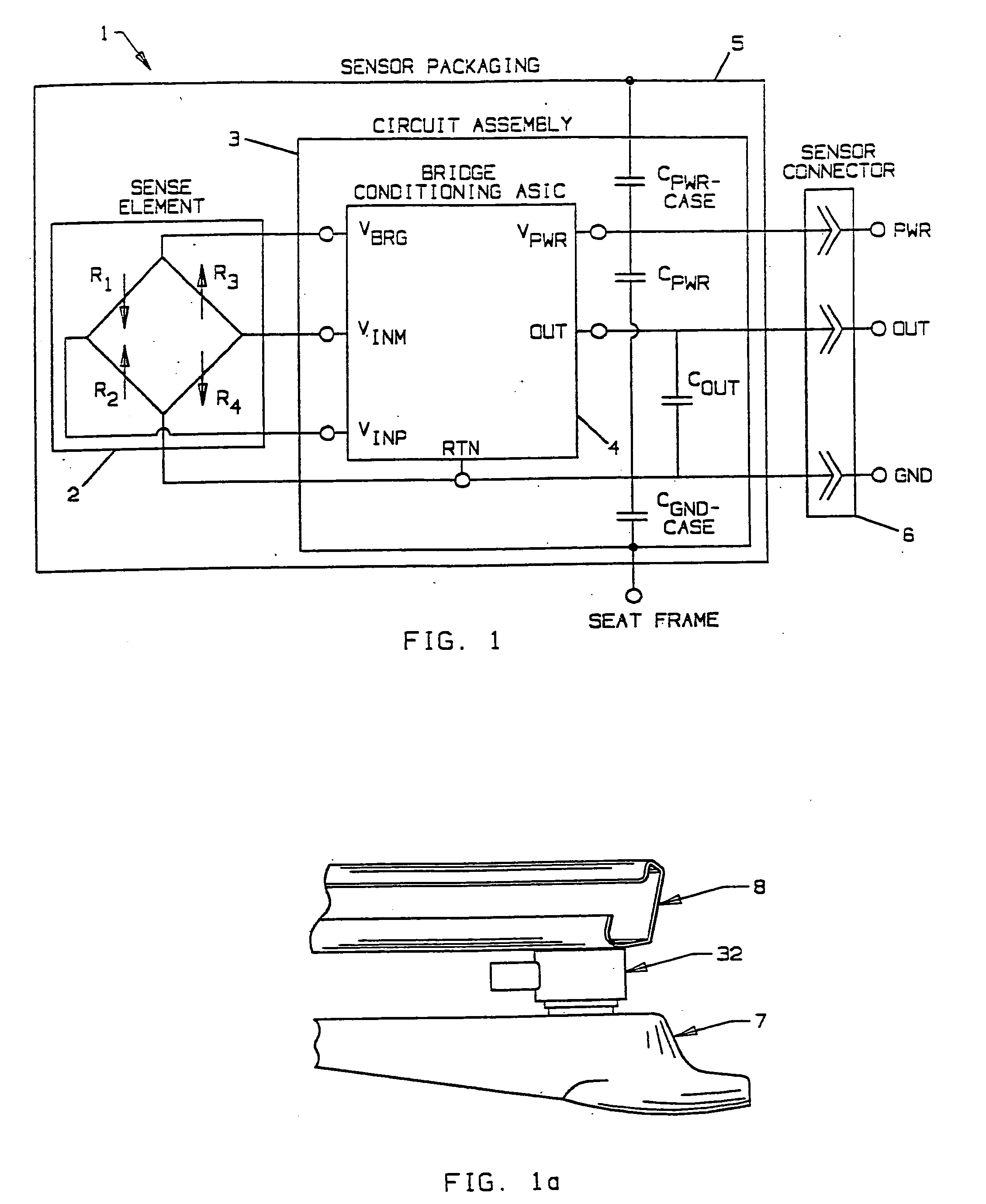
[0027] Occupant weight sensors made in accordance with the invention employ monocrystalline silicon strain gauge technology to convert mechanical inputs from the system, i.e., the weight of the occupant of the seat into electrical signals. Such technology used for various automotive pressure sensing applications is known, as shown and described in U.S. Pat. No. 6,453,747, assigned to the assignee of the present invention, the subject matter of which is incorporated herein by this reference.

[0028] Mechanical input to the sensor produces stress in the silicon piezoresistors which have the property in which their resistance undergoes a relative change in proportion to the applied stress. The piezoresistor effect in monocrystalline silicon is extremely strong with an equivalent gauge factor of approximately 150. This feature enables strong signal to noise ratios compared to other strain gauge technologies such as bonded metal foil or thick film ink with gauge factors in the range of ap...


PUM


Abstract

An occupant weight sensor (1) for placement between a frame (7) fixed to the chassis of a vehicle and a second frame (8) supporting a vehicle seat has a sense element having a first body (12, 22, 28, 34, 50, 62, 64, 68) formed with a planar sense surface on which are mounted piezoresistors electrically connected in a Wheatstone bridge configuration. A post (12a, 22c, 28c, 34e, 50b, 62a, 64a, 68b) extends outwardly from the first body for attachment to the first frame. A second body is formed with a force transfer portion (14a, 24g, 30d, 36b, 52a, 70a) permanently attached to the first body along an outer periphery circumscribing the sense surface. The piezoresistors are electrically connected to conditioning electronics received in a chamber formed between the two bodies. The effects of parasitic loads on the sense element are minimized by selected placement of the piezoresistors on the sense surface. Several variations are disclosed for attaching the sensor to the first and second frames and both longitudinally and laterally extending electrical connectors are shown.

Description

CROSS REFERENCE TO RELATED APPLICATIONS [0001] U.S. application Ser. Nos. ______ (Attorney Docket Nos. ______), filed ______ and ______ respectively, and both assigned to the assignee of the present invention contain subject matter related to the subject matter of this application.FIELD OF THE INVENTION [0002] This invention relates generally to weight sensors and more particularly to weight sensors used for weighing occupants of a vehicular seat in order to prevent or modify airbag deployment for improved safety of the seat occupant. BACKGROUND OF THE INVENTION [0003] Governmental legislation requires the development of a system capable of sensing information related to front passenger seat occupants and classifying such occupants to the extent necessary to adapt airbag deployment to improve passenger safety. For example, airbag deployment can be a problem for small children or children in car seats occupying a front passenger seat. Using information provided by vehicular seat weig...

Claims


Application Information

Patent Timeline
IPC IPC(8): B60R21/01G01G3/14B60R21/015G01G19/12G01G19/414G01G19/52G01G23/01
CPCG01G19/4142B60R21/0152B60R21/01516
Inventor MCBRIDE, TIMOTHY M.O'BRIEN, EDWARD F.HATCH, DAVID P.
Owner SENSATA TECHNOLOGIES INC
Why Eureka
Try Eureka