
Adjustable Mounting Assembly for Ceiling Fixtures

a technology for mounting assemblies and ceiling fixtures, which is applied in the direction of machine supports, domestic objects, applications, etc., can solve the problems of limiting the range of locations where fixtures may be placed, unable to direct joist connections, and the ceiling covering material is not designed to support loads. , to achieve the effect of simple and effectiv

Inactive Publication Date: 2009-06-18
LONGTON MICHAEL JOHN +1
View PDF12 Cites 15 Cited by
  • Summary
  • Abstract
  • Description
  • Claims
  • Application Information

AI Technical Summary

Benefits of technology

[0008]It is, therefore, an object of the present invention to provide a simple and effective mounting assembly for ceiling fixtures capable of accommodating a wide variety of joist structures in a ceiling and including an adjustable carrier bracket.
[0009]It is another object of the present invention to provide an inexpensive mounting assembly for ceiling fans and other fixtures that is easily and efficiently installed.
[0011]Preferably, the carrier bracket is adapted to move axially along the tube, whereby axial movement of the carrier bracket along the tube allows the downwardly facing aperture to align with a desired position of the fixture on the ceiling.

Problems solved by technology

The ceiling covering material is not designed to support loads perpendicular to its surface.
To achieve this, a fixture should be secured directly to a joist, however, this limits the range of locations where the fixture may be placed.
Such a limitation is problematic since it is often desirable to place the fixture in a specific position on the ceiling.
Therefore, if no joist is positioned at or near the desired position, direct joist connection is not possible.
Known mounting assemblies for ceiling fixtures are awkward to install.
Securing the brace to the joists becomes difficult if the brace was cut to the incorrect size, or was not in the correct position when marking the installation points.

Method used


Image

  • Adjustable Mounting Assembly for Ceiling Fixtures
  • Adjustable Mounting Assembly for Ceiling Fixtures
  • Adjustable Mounting Assembly for Ceiling Fixtures

Examples


Embodiment Construction

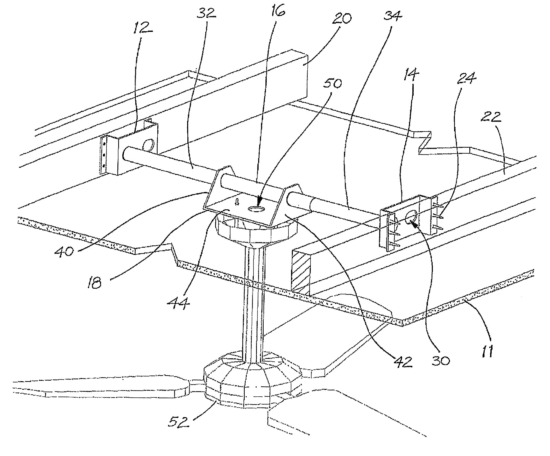
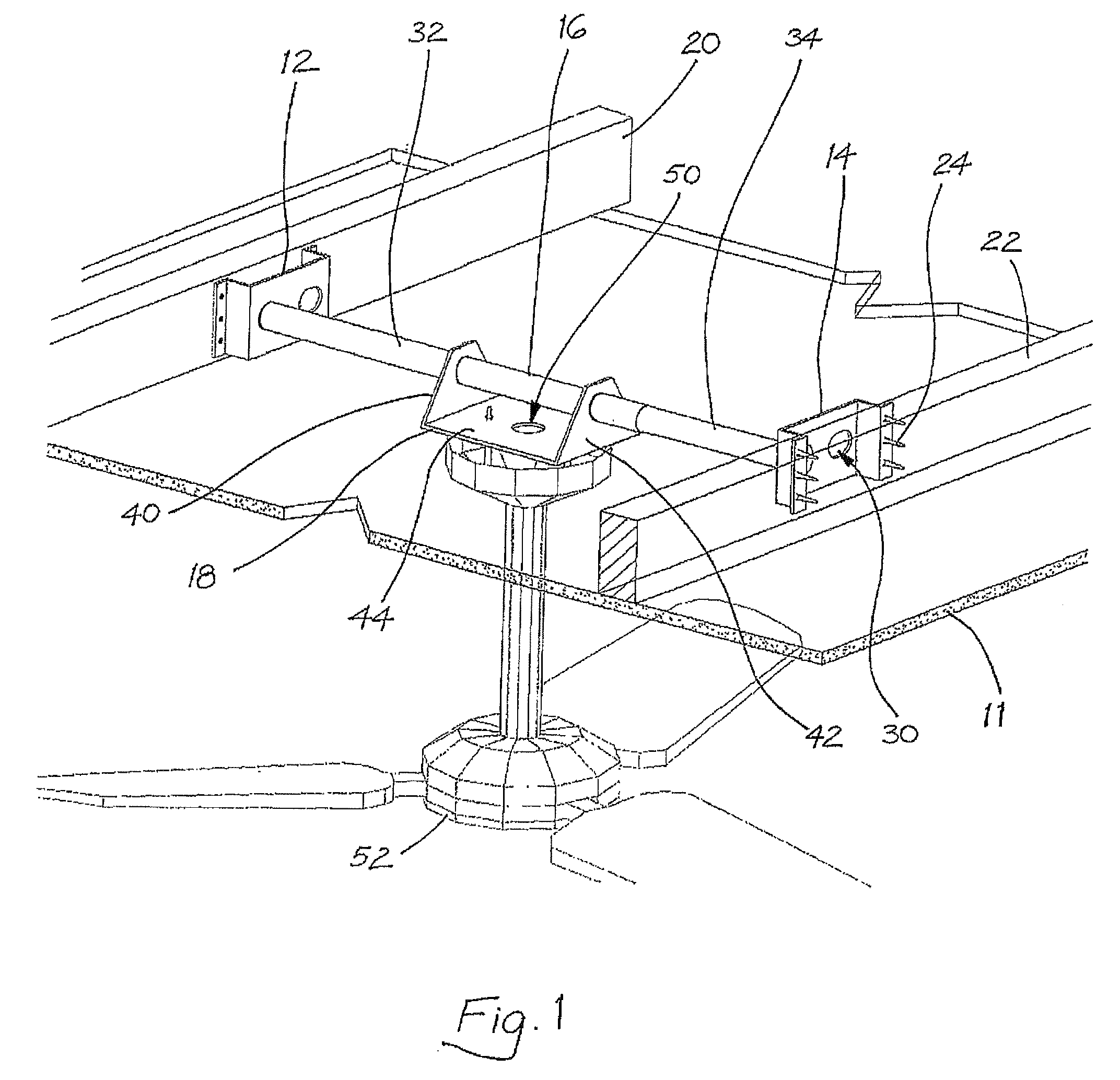
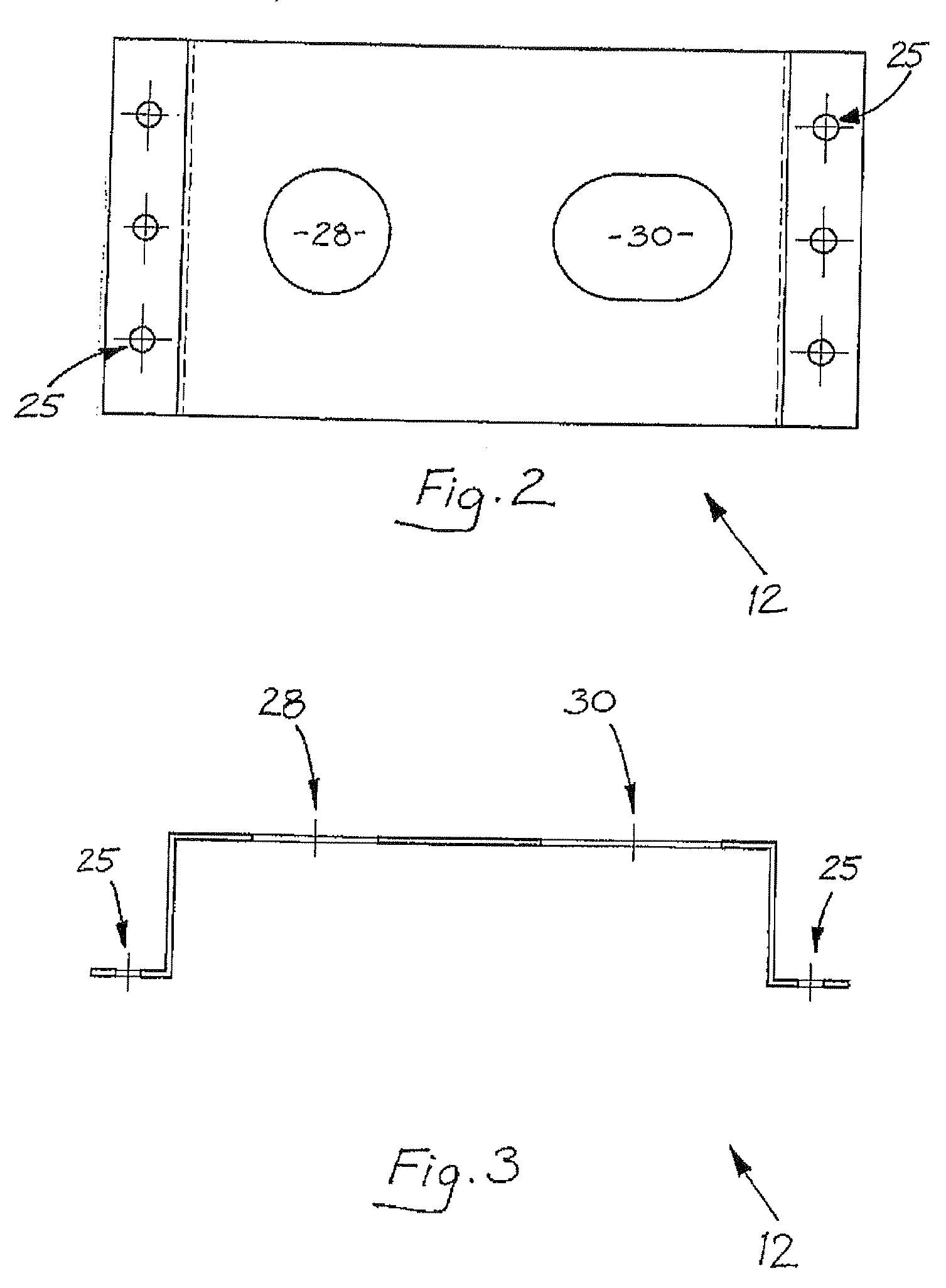
[0031]The adjustable mounting assembly shown installed on a ceiling 11 in FIG. 1 has a pair of opposingly spaced apart mounting brackets 12, 14 (one bracket of the pair being shown in FIGS. 2 and 3), a telescopic tube 16 (first and second tubular members of the tube 16 being shown in FIGS. 4 and 5), and a carrier bracket 18 (as shown in FIGS. 6 and 7).

[0032]The mounting brackets 12, 14 are mounted onto a pair of spaced apart ceiling joists 20, 22, respectively, by a plurality of screws 24 engaged through screw holes 25. The mounting brackets 12, 14 include means, in the form of apertures 28, 30, for receiving therebetween the telescopic tube 16. The apertures 28 are circular so as to receive the telescopic tube 16 perpendicularly when the ceiling joists are parallel as shown in FIG. 1. The apertures 30 are oval shaped so as to receive the telescopic tube 16 obliquely when the ceiling joists are not parallel, such as when they are perpendicular.

[0033]Alternatively, the mounting brack...


PUM


Abstract

An adjustable mounting assembly for ceiling fixtures has a pair of opposingly spaced apart mounting brackets (12,14) for mounting onto respective ones of a pair of spaced apart ceiling joists (20,22). The mounting brackets (12,14) include apertures (28,30) which receive therebetween a telescopic tube (16) comprising a first tubular member (32) and a second tubular member (34) being slidably received within the first tubular member (32). The first and second tubular members (32,34) are movable in opposing axial directions between a retracted position and an extended position to suit a distance between the ceiling joists (20,22). The telescopic tube (16) has mounted thereon a carrier bracket (18) which is adapted to move axially along the telescopic tube (16). The carrier bracket (18) includes a downwardly facing aperture (50) and axial movement of the carrier bracket (18) along the telescopic tube (16) allows the downwardly facing aperture (50) to align with the desired position of the fixture on the ceiling.

Description

FIELD OF THE INVENTION[0001]The present invention relates to an adjustable mounting assembly for ceiling fixtures, such as ceiling fans, chandeliers, light fittings and electrical junction boxes for the aforementioned devices. In particular, the present invention relates to a mounting assembly that is adjustable in length and orientation and so can be secured between ceiling joists that are spaced at different distances apart, and at different angles to each other. More particularly, the present invention relates to an adjustable mounting assembly having a movable carrier bracket which can be readily aligned with a desired position of a ceiling fixture.BACKGROUND OF THE INVENTION[0002]Ceilings are typically constructed of structural members including a plurality of spaced apart joists which support a ceiling covering material, such as plaster or a gypsum board often referred to as “gyprock”.[0003]In this specification and claims, the term “joist” includes within its meaning a joist-...

Claims


Application Information

Patent Timeline
IPC IPC(8): F16M13/00
CPCF04D25/088F16M13/027F16M13/02F04D29/601
Inventor LONGTON, MICHAEL JOHNHARRISS, PAUL
Owner LONGTON MICHAEL JOHN
Learn More