Seatback Frame Structure For Vehicles

a frame structure and vehicle technology, applied in the field of seatback frame structure, can solve the problems of reduced freedom of design, increased manufacturing costs and weight, and low frame compatibility between different kinds of vehicles, and achieve the effect of improving the frame compatibility between vehicles

Active Publication Date: 2009-06-18
HYUNDAI MOTOR CO LTD +1
View PDF9 Cites 17 Cited by
  • Summary
  • Abstract
  • Description
  • Claims
  • Application Information

AI Technical Summary

Benefits of technology

[0013]Various aspects of the present invention provide for a seatback frame structure for vehicles, with which it is possible to adjust the height of a seatback, and round a side of the seatback, so that an additional side bracket is not required depending on the kind of vehicle, and thus frame compatibility between vehicles is considerably improved, and various designs may be applied.

Problems solved by technology

Thus, the conventional seatback frame structure 110 has a problem in that frame compatibility between different kinds of vehicles is low, so that the freedom of design is reduced.
The conventional seatback frame structure 110 has another problem in that each pole guide 140 is secured to the upper cross member 130 using a pole guide tube 145, so that manufacturing costs and weight are increased, due to the use of an additional component, namely the pole guide tube 145.
The conventional seatback frame structure 110 has a further problem in that product variation and welding variation are caused by the increase in the number of components, and thus gaps or other defects related to the coupling of the headrest may occur, and thus operating efficiency is low.
Thus, in the event of a head-on collision, the head of a passenger, who sits in the back seat, collides with the exposed edge 132, so that the passenger may be injured, and thereby vehicle safety legislation may not be satisfied.
Further, space for mounting a power motor in the upper cross member 130 is insufficient, and working space is small because of the rear edge 132, so that productivity is deteriorated.

Method used


Image

  • Seatback Frame Structure For Vehicles
  • Seatback Frame Structure For Vehicles
  • Seatback Frame Structure For Vehicles

Examples


Embodiment Construction

[0028]Reference will now be made in detail to various embodiments of the present invention(s), examples of which are illustrated in the accompanying drawings and described below. While the invention(s) will be described in conjunction with exemplary embodiments, it will be understood that present description is not intended to limit the invention(s) to those exemplary embodiments. On the contrary, the invention(s) is / are intended to cover not only the exemplary embodiments, but also various alternatives, modifications, equivalents and other embodiments, which may be included within the spirit and scope of the invention as defined by the appended claims.

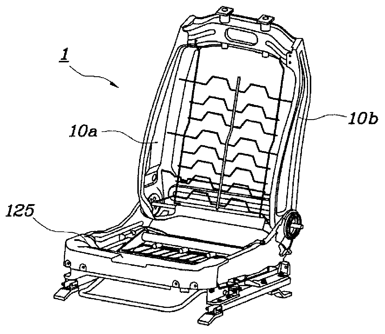
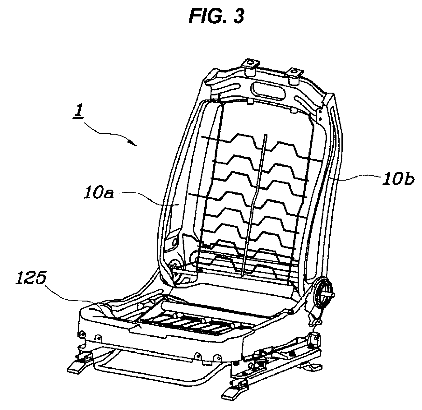
[0029]As shown in FIG. 3, a seatback frame structure 1 includes a pair of side brackets 10a and 10b, which are rotatably coupled at lower ends thereof to a seat frame 125.

[0030]The side brackets 10a and 10b are spaced apart from each other, and an upper cross member 20 is transversely provided between the upper ends of the side bracke...


PUM


Abstract

A seatback frame structure is provided for the manufacture of a seat of a vehicle. The seatback frame structure includes a pair of side brackets and an upper cross member. The side brackets are coupled at lower ends thereof to left and right sides of a seat frame. The upper cross member is transversely mounted between the upper ends of the side brackets, and a headrest is placed on the upper portion of the upper cross member. Each of opposite ends of the upper cross member comprises a downwardly inclined surface, and is coupled to the upper end of a corresponding side bracket.

Description

CROSS-REFERENCE TO RELATED APPLICATION[0001]The present application claims priority to Korean Application No. 10-2007-0133182 filed Dec. 18, 2007, the entire contents of which applications is incorporated herein for all purposes by this reference.BACKGROUND OF THE INVENTION[0002]1. Field of the Invention[0003]The present invention relates to a seatback frame structure for manufacturing a seat of a vehicle.[0004]2. Description of Related Art[0005]As well known to those skilled in the art, a vehicle seat includes a seat portion on which a passenger sits, a back portion against which a passenger's back rests, and a headrest which supports the neck and the head. Such a vehicle seat is designed to offer comfort to a passenger when he or she sits in the seat, in addition to ensuring the safety of the passenger.[0006]A conventional frame structure used for such a vehicle seat is shown in FIG. 1.[0007]In a conventional seatback frame structure 110 for vehicles, left and right side brackets ...

Claims


Application Information

Patent Timeline
Patent Type & Authority Applications(United States)
IPC IPC(8): B60N2/68A47C7/40A47C7/02B60N2/90
CPCB60N2002/2204B60N2/68B60N2/64
Inventor SUNG, YOUNG BOKPARK, SANG DO
Owner HYUNDAI MOTOR CO LTD
Why Eureka
Try Eureka