Reproducer, digital camera, slide show reproduction method, program, image display apparatus, image display method, image reproduction method, and image display program

Inactive Publication Date: 2009-06-18
OM DIGITAL SOLUTIONS CORP
View PDF6 Cites 32 Cited by
  • Summary
  • Abstract
  • Description
  • Claims
  • Application Information

AI Technical Summary

Benefits of technology

[0014]According to a first aspect of the present invention, there is provided a reproducer for performing slide show reproduction in which a plurality of images is continuously reproduced, comprising: a storage part which stores the images; a vibration detection part which detects a vibration operation of the reproducer by a user; a switching instruction part which instructs switching of reproduction content in the

Problems solved by technology

Among these methods, the slide show simply displays digital

Method used


Image

  • Reproducer, digital camera, slide show reproduction method, program, image display apparatus, image display method, image reproduction method, and image display program
  • Reproducer, digital camera, slide show reproduction method, program, image display apparatus, image display method, image reproduction method, and image display program
  • Reproducer, digital camera, slide show reproduction method, program, image display apparatus, image display method, image reproduction method, and image display program

Examples


first embodiment

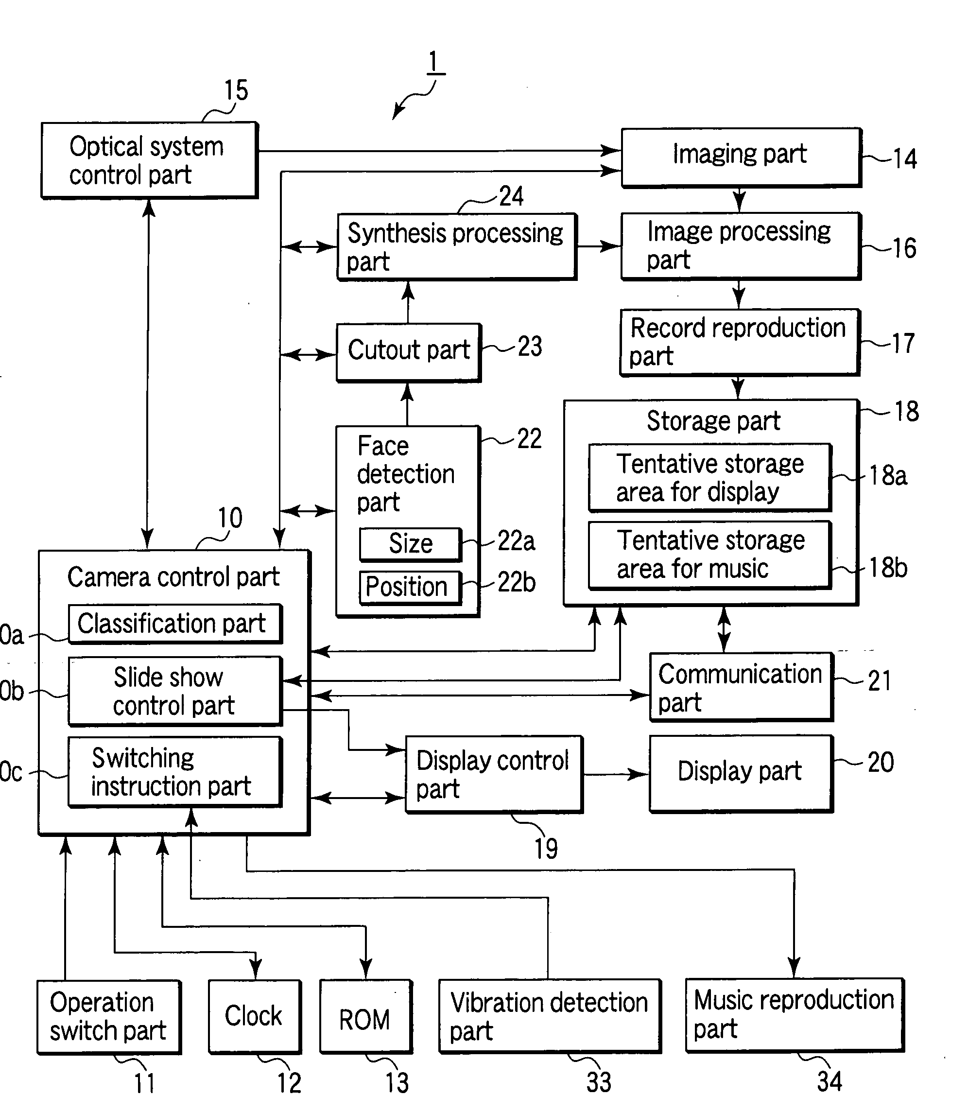
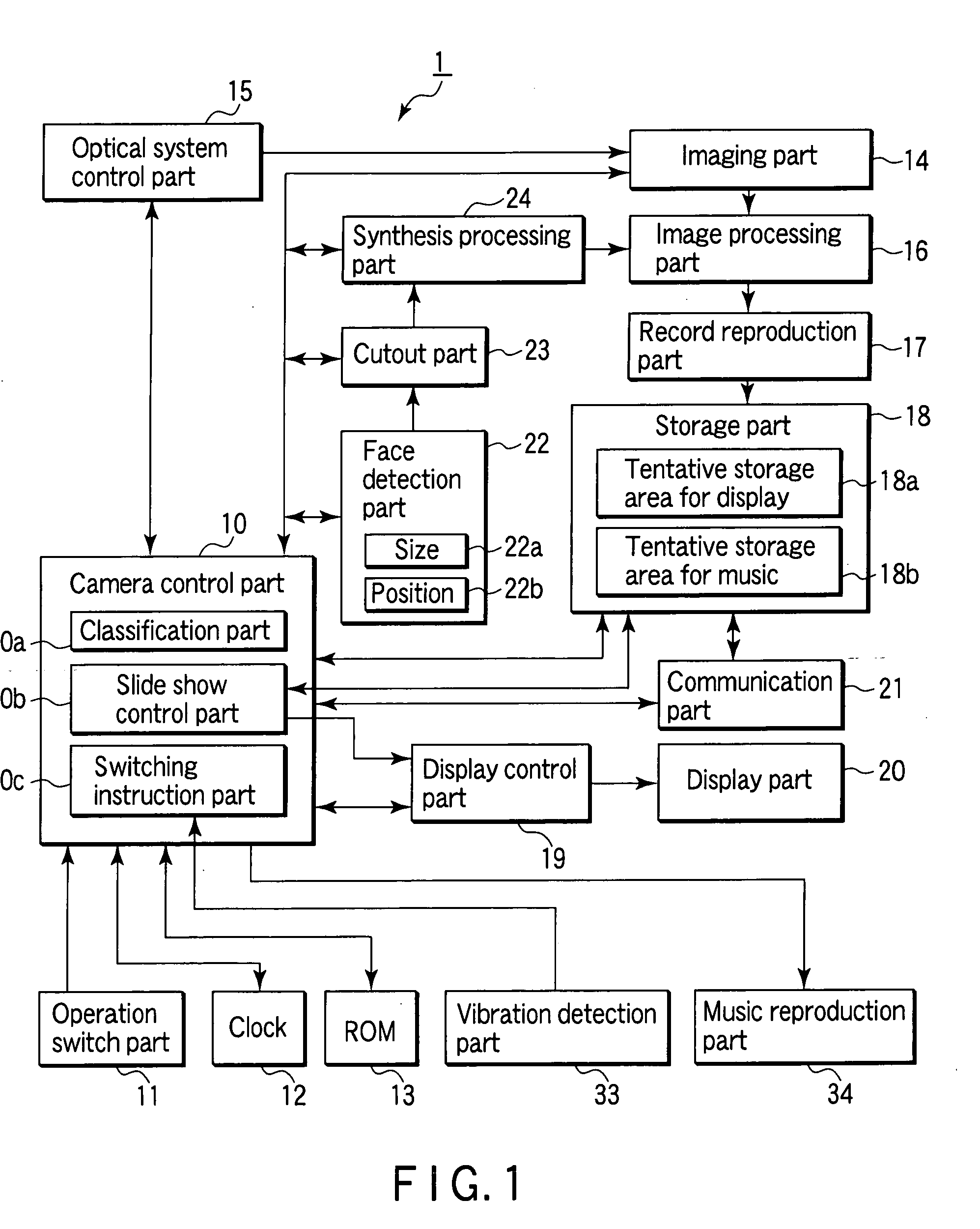
[0071]FIG. 1 is a block diagram showing the configuration of a digital camera according to the first embodiment of the present invention. As shown in FIG. 1, a digital camera 1 has a camera control part 10, an operation switch part 11, a clock part 12, a ROM 13, an imaging part 14, an optical system control part 15, an image processing part 16, a record reproduction part 17, a storage part 18, a display control part 19, a display part 20, a communication part 21, a face detection part 22, a cutout part 23, a synthesis processing part 24, a vibration detection part 33, and a music reproduction part 34.

[0072]The camera control part 10 centrally controls the whole camera based on a program stored in the ROM 13. However, for convenience of description, the camera control part 10 is assumed here to have a classification part 10a for performing classification processing (details will be provided later), a slide show control part 10b for performing slide show reproduction control processin...

second embodiment

[0186]A camera according to the second embodiment of the present invention will be described below. FIG. 11 is a block diagram showing the configuration of a camera 10 according to the second embodiment of the present invention. The camera 10 is a digital camera and has a control part 1, an imaging part 2, an optical system control part 3, a recording part 4, a face detection part 5, a cutout part 6, a synthesis processing part 7, a display part 8, a display control part 8a, a clock part 9, an operation determination part 11, a position information part 12, and a communication part 14. The camera 10 can also be connected to a database 20 with a search function in an external server via an Internet network 15.

[0187]The control part 1 is connected to each part of the camera 10 and centrally controls the whole camera 10 in accordance with an operation of an operation member or the like determined by the operation determination part 11 following timing control by a timing control part 1...


PUM


Abstract

A reproducer is provided with members shown below. Namely, the reproducer is provided with a storage part for storing images, a vibration detection part for detecting a vibration operation by a user, a switching instruction part for instructing switching of reproduction content in slide show reproduction based on a detection result from the vibration detection part, a synthesis processing part for performing creation processing of slide show images, which are images for the slide show reproduction, based on instructions of the switching instruction part, and a slide show control part for performing the slide show reproduction of the images stored in the storage part and the slide show images.

Description

CROSS-REFERENCE TO RELATED APPLICATIONS[0001]This application is based upon and claims the benefit of priority from prior Japanese Patent Applications No. 2007-316070, filed Dec. 6, 2007; and No. 2008-008775, filed Jan. 18, 2008, the entire contents of both of which are incorporated herein by reference.BACKGROUND OF THE INVENTION[0002]1. Field of the Invention[0003]The present invention relates to a reproducer for reproducing a slide show, a digital camera, a slide show reproduction method, a program, an image display apparatus that effectively switches a plurality of image shots to display the image shots, an image display method, and an image display program.[0004]2. Description of the Related Art[0005]In recent years, with the widespread use of digital cameras, recording media for recording digital data are also growing in capacity, and when compared with the age when film cameras were mainly used, a large quantity of images can now be shot easily.[0006]In view of such circumstan...

Claims


Application Information

Patent Timeline
IPC IPC(8): H04N5/228H04N5/76H04N5/222G06K9/00
CPCG06F3/017G06F3/0487G06K9/00221G11B27/034G11B27/28H04N5/23219H04N5/23229H04N5/23248H04N5/23293H04N5/2625H04N5/765H04N5/772H04N9/8205G06F3/04847G06F3/0346G06V40/16H04N23/61H04N23/611H04N23/80H04N23/68H04N23/63
Inventor NONAKA, OSAMUSHIMURA, KAZUHIKOUEMURA, TATSUYUKI
Owner OM DIGITAL SOLUTIONS CORP
Why Eureka
Try Eureka