LED lamp

a technology of led lamps and led lamps, applied in the field of led lamps, can solve the problems of increased power consumption, increased heat output, and increased cost of modules, and achieve the effect of generating light reliably and uniform brightness

Inactive Publication Date: 2009-06-18
FU ZHUN PRECISION IND SHENZHEN +1
View PDF9 Cites 22 Cited by
  • Summary
  • Abstract
  • Description
  • Claims
  • Application Information

AI Technical Summary

Benefits of technology

[0008]An LED lamp, includes a frame, a heat sink, an LED module and a reflector. The frame comprises a base, an upper ring spaced from the base and a plurality of stanchions connecting the upper ring and the base together. The heat sink is coupled to a top of the upper ring and covers a whole of a top of the frame. The LED module is attached to a bottom surface of the heat sink and surrounded by the upper ring. The reflector is placed on the base and has an outer surface facing and being slantwise to the LED module. The reflector has an inverted funnel-like shape with a hollow pipe extending upwardly toward a center of the LED module. The outer surface of the reflector is configured into a multiple-stepped sections, whereby light generated by the LED module can be reflected by the reflector in every directions to radiate out of the LED lamp. Accordingly, the LED lamp can have a soft light with an even brightness. Furthermore, heat generated by the LED module is absorbed by the heat sink to be dissipated into ambient air, whereby the LED lamp can reliably generate light for a sufficiently long period of time.

Problems solved by technology

The large number of LEDs leads to a more expensive module and one with greater power consumption.
The greater power usage leads to greater heat output, which, if not adequately addressed at additional expense, impacts the LED lamp reliability.
Besides, since the LEDs are generally arranged on a printed circuit board which having a flattened surface, the LEDs acting as a light source and arranged in this way usually are failed to provide a three-dimensional, soft lamplight with even brightness that is required for some applications, for example, a park lamp or a decorative lamp.

Method used


Image

  • LED lamp
  • LED lamp
  • LED lamp

Examples


Embodiment Construction

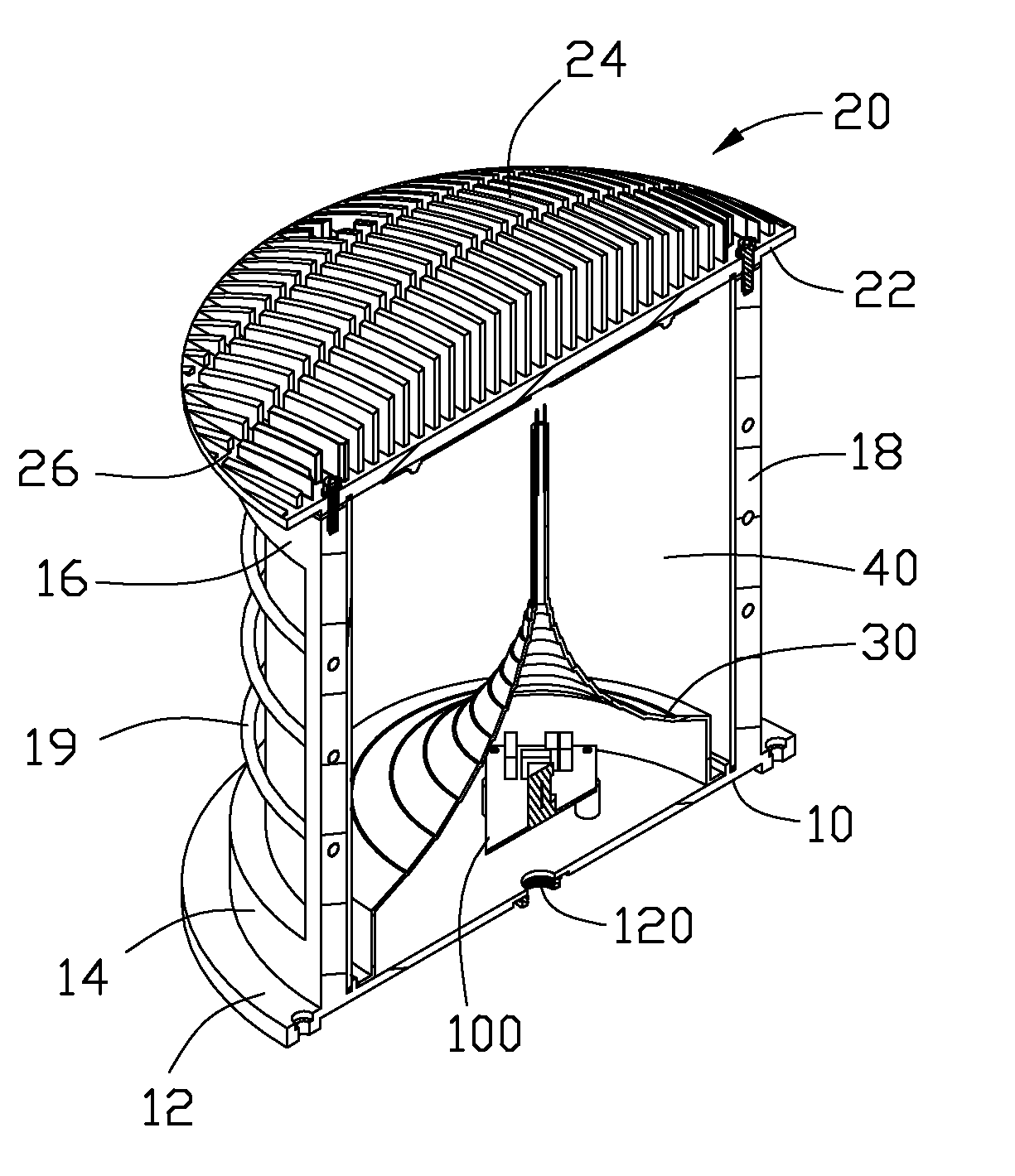
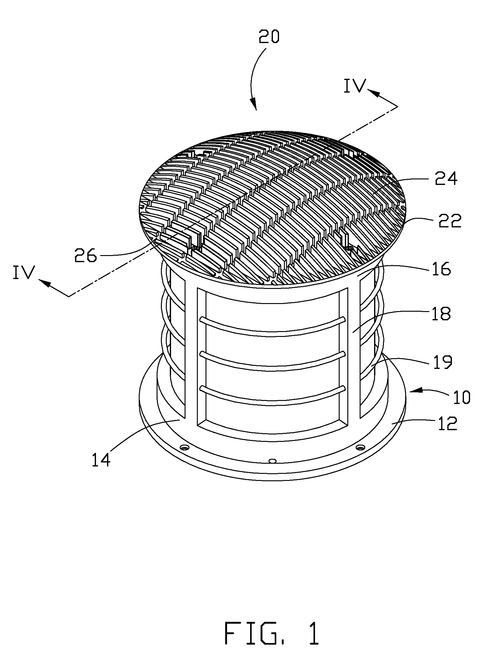
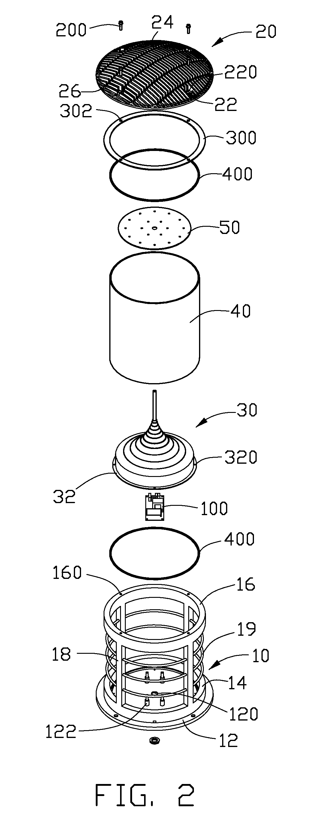
[0015]Referring to FIGS. 1-3, an LED lamp in accordance with a preferred embodiment is illustrated. The LED lamp comprises a frame 10, a heat sink 20 disposed on the frame 10, an LED module 50 attached to a bottom surface of the heat sink 20, a reflector 30 disposed in the frame 10, and an envelope 40 fitly received in the frame 10 and surrounding the reflector 30.

[0016]The frame 10 is formed integrally and configured to provide a solid support of the LED lamp. The frame 10 comprises a circular plate-shaped base 12, a lower ring 14 extending upwardly from a top surface of the base 12, an upper ring 16 spaced from the lower ring 14 and a plurality of vertical stanchions 18 connecting the lower and the upper rings 14, 16 together. The base 12 defines a holding hole 120 in a centre thereof, for extension of lead wires into the LED lamp and receiving a lamp holder to hold the LED lamp in position. Four fixing posts 122 surrounding the holding hole 120 extend upwardly from a top surface ...


PUM


Abstract

An LED lamp includes a frame, a heat sink, an LED module and a reflector. The frame comprises a base, an upper ring spaced from the base and a plurality of stanchions connecting the upper ring and the base together. The heat sink is coupled to a top of the upper ring and covers a whole of a top of the frame. The LED module is attached to a bottom surface of the heat sink and surrounded by the upper ring. The reflector is placed on the base and has an outer surface facing and slantwise to the LED module. The reflector has a configuration like an inverted funnel. The outer surface of the reflector has multiple steps formed thereon.

Description

BACKGROUND OF THE INVENTION[0001]1. Field of the Invention[0002]The present invention relates to an LED lamp for a lighting purpose, and more particularly to an improved LED lamp providing soft light having even brightness. Furthermore, the LED lamp has a good heat dissipation capability so that the LED lamp can be used for a long time with a good illumination quality.[0003]2. Description of Related Art[0004]An LED lamp is a type of solid-state lighting that utilizes light-emitting diodes (LEDs) as a source of illumination. An LED is a device for transferring electricity to light by using a theory that, if a current is made to flow in a forward direction through a junction region comprising two different semiconductors, electrons and holes are coupled at the junction region to generate a light beam. The LED has an advantage that it is resistant to shock, and has an almost eternal lifetime under a specific condition; thus, the LED lamp is intended to be a cost-effective yet high qual...

Claims


Application Information

Patent Timeline
Patent Type & Authority Applications(United States)
IPC IPC(8): F21V7/00
CPCF21K9/00F21V7/0008F21V15/02F21V23/02F21V29/004F21V29/763F21V31/005F21W2111/06F21W2121/00F21V29/75F21Y2101/02F21V29/74F21Y2115/10
Inventor ZHANG, WEN-XIANGYU, GUANGLAI, CHENG-TIEN
Owner FU ZHUN PRECISION IND SHENZHEN
Why Eureka
Try Eureka