Micro-mechanical part with a shaped aperture for assembly on a shaft

a micro-mechanical and shaft-shaped technology, applied in the field of micro-mechanical parts, can solve the problems of high risk of parts being broken during assembly, high risk of parts being detached or moving elements not being driven by shafts, drawbacks of additional machining steps, etc., and achieve the effect of any risk of breaking

Active Publication Date: 2009-06-18
NIVAROX FAR
View PDF7 Cites 33 Cited by
  • Summary
  • Abstract
  • Description
  • Claims
  • Application Information

AI Technical Summary

Benefits of technology

[0008]It is thus an object of the present invention to overcome the drawbacks of the aforecited prior art by providing a micro-mechanical part, ...

Problems solved by technology

When the material does not have any, or very little, plastic region, which is the case of glass, quartz or silicon, there is a high risk of the part being broken during assembly.
If a push fit is made to prevent stresses in the brittle material, there is then a risk of the part becoming detached or a moving element not being driven by the shaft.
The use of an adh...

Method used


Image

  • Micro-mechanical part with a shaped aperture for assembly on a shaft
  • Micro-mechanical part with a shaped aperture for assembly on a shaft
  • Micro-mechanical part with a shaped aperture for assembly on a shaft

Examples


first embodiment

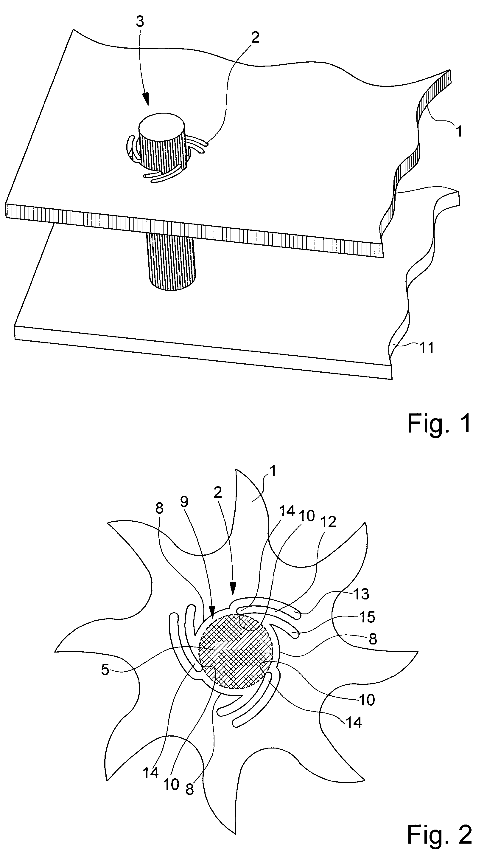
[0030]A first embodiment will be described with reference to FIGS. 1 and 2. FIG. 1 shows a perspective view of a portion of plate 1 that has to be fixed to a support block 11 by means of a cylindrical stud 3 passing through an aperture 2 formed in said plate 1.

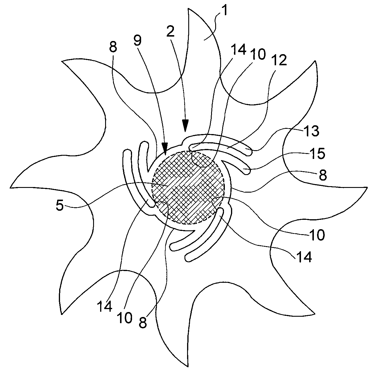
[0031]Plate 1 is formed of a brittle material, i.e. a material that has no plastic region within normal use temperatures, such as glass, quartz or silicon. Plate 1 can simply form a construction element, for example a bottom plate, a bridge or a dial of a timepiece. It may also have a functional role, carrying a printed circuit board or a Micro-Electro-Mechanical Systems (MEMS) that has to be secured to block 11. In order to avoid breaking the part during a driving-in assembly, aperture 2 is a shaped aperture shown in a larger scale top view in FIG. 2.

[0032]FIG. 2 shows by way of example a silicon escape wheel mounted on a cylindrical shaft 5 to be pivoted between two bearings. As can be seen, the contour of aperture 2 does no...

third embodiment

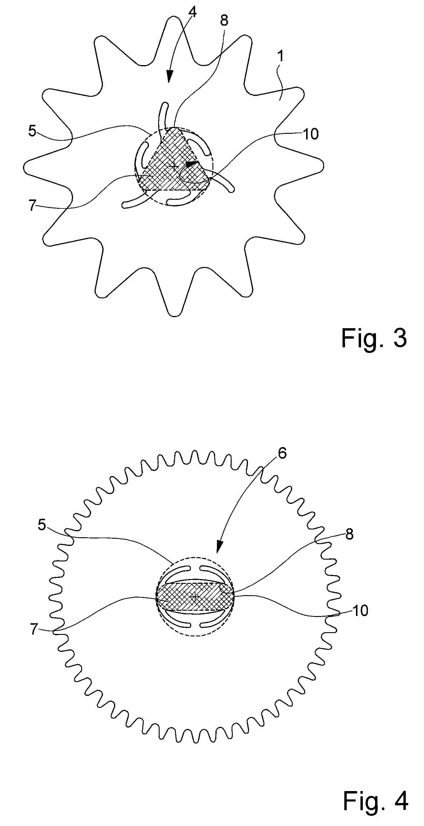
[0038]FIG. 4 shows a third embodiment in which the part, made for example of silicon, is a toothed wheel having at the centre thereof a shaped aperture 6, which, as previously, has an “anti-rotational” function. In this example the shaped aperture 7 is oblong.

[0039]It is of course possible to imagine any other non-circular contour able to provide an anti-rotational effect, without departing from the scope of the present invention.

[0040]It is also possible, in any of the embodiments that have just been described to provide the ends 14 of resilient deformation zones 10 and shaft 5 with surface roughness, for example flutes, to further reduce the risk of the part rotating on the shaft.

[0041]The examples given in the preceding description concern parts that rotate continuously, but it is clear that those skilled in the art could adapt the same principle to parts having an alternate movement, such as a lever, a pivoting part, a collet, a pallet or an escape wheel.

[0042]Depending upon the...


PUM

PropertyMeasurementUnit
Shapeaaaaaaaaaa
Brittlenessaaaaaaaaaa
Deformation enthalpyaaaaaaaaaa

Abstract

The part is made from a plate (1) made of a brittle material, such as glass, quartz or silicon and includes at least one aperture (2, 4, 6) for driving in a shaft (5). This aperture is characterized in that it includes alternately rigidifying and positioning zones (8) and resilient deformation zones (10). Application to securing a shaft onto the moving parts of a timepiece movement.

Description

FIELD OF THE INVENTION[0001]The present invention concerns a micro-mechanical part comprising a shaped aperture for facilitating assembly on a shaft for a moving part, or on a stud for a fixed part, and limiting or removing the risk of the part breaking when it is driven onto the shaft or stud, particularly when said part is made of a brittle material.BACKGROUND OF THE INVENTION[0002]In the field of micro-mechanics, which will hereafter be more specifically illustrated by the field of horology, the driving in technique is very widely used, for example for fixing a wheel onto a shaft. When the material forming the part has a plastic region, which is the case of metals and alloys, the tolerances necessary for the shaft and bore can be calculated so as to obtain a tight fit without any risk of breaking the part, or deforming it. When the material does not have any, or very little, plastic region, which is the case of glass, quartz or silicon, there is a high risk of the part being brok...

Claims


Application Information

Patent Timeline
IPC IPC(8): G04B29/00
CPCG04B13/022Y10T29/49465Y10T403/4634G04B15/14
Inventor VAUCHER, FREDERICGABUS, RAYMONDVERARDO, MARCO
Owner NIVAROX FAR
Why Eureka
Try Eureka