

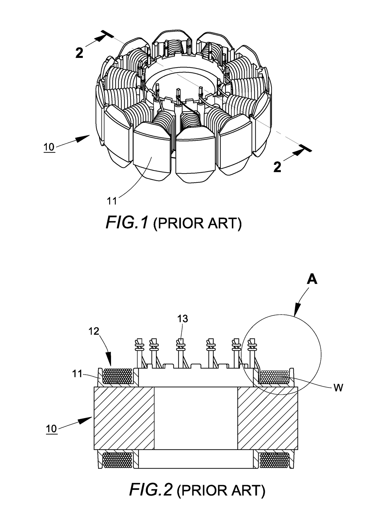
Method of winding a stator core to prevent breakage of wire between pin and winding groove
a stator core and winding groove technology, applied in windings, inductance/transformers/magnets, magnetic circuit shapes/forms/construction, etc., can solve the problems of 0.5% defect rate of stator winding products made by existing mass manufacturing processes, and inoperative entire brushless dc motors. , to achieve the effect of preventing overtension and breaking
- Summary
- Abstract
- Description
- Claims
- Application Information
AI Technical Summary
Benefits of technology
Problems solved by technology
Method used
Image

Examples
first embodiment
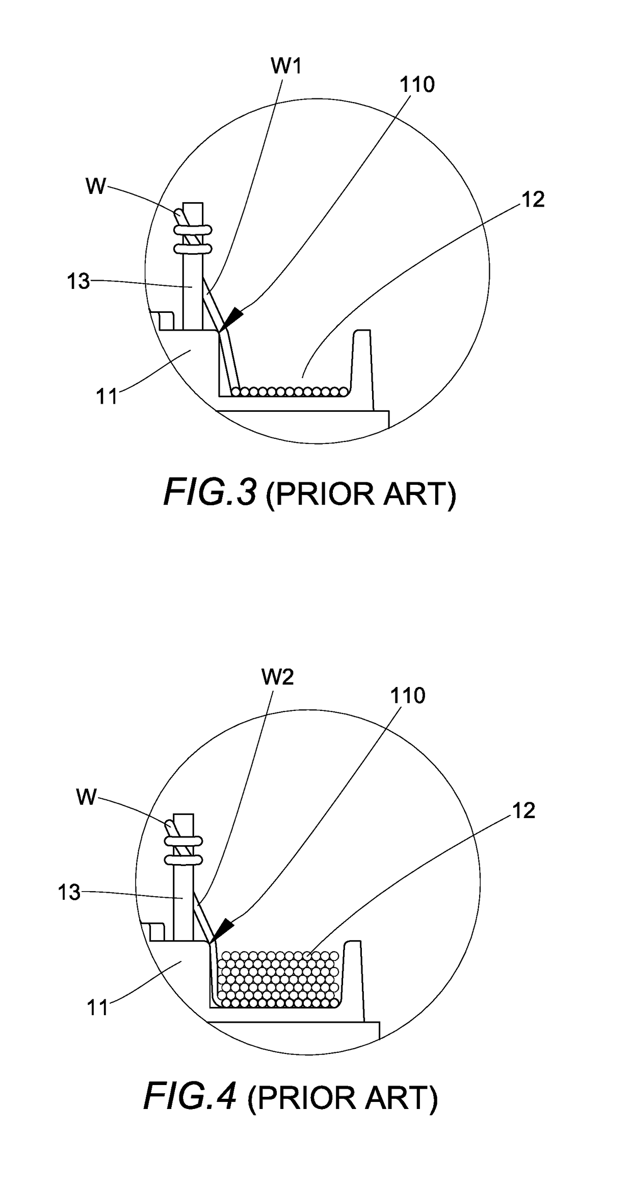
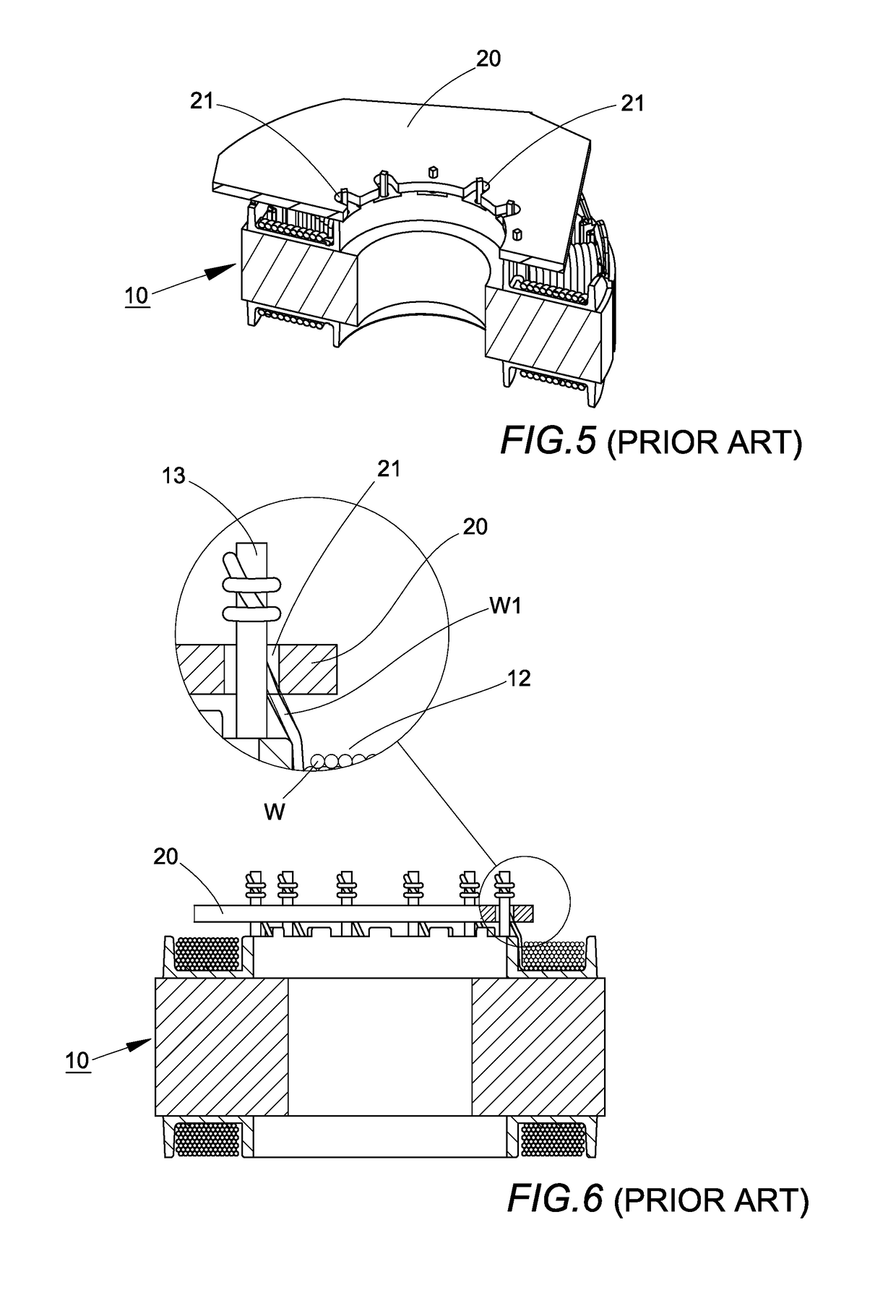
[0017]FIG. 7 shows a method for preventing enameled wire between a pin and a winding groove on an insulating stator base from breakage. The method comprises controlling a tension servo of an automatic wire-winding machine to first wind the enameled wire W tightly around the pin 13 of the insulating stator base 11, then to wind the enameled wire W around the pin 13 to form at least one winding that loosely encircles the pin 13 so that the loose winding forms a gap G with the pin 13, and afterward to draw the enameled wire W into the winding groove 12 of the insulating stator base 11 to form windings that tightly encircle the insulating stator base 11 within the groove 12. Consequently, in the process where the enameled wire W forms layers of windings in the winding groove 12, the enameled wire segment W2 between the pin 13 and the winding groove 12 with the gap G formed by the at least one loose winding provides a margin that compensates for the compression that would otherwise be ca...
second embodiment
[0018]FIG. 8 shows a method for preventing enameled wire between a pin and a winding groove on an insulating stator base from breakage. The method comprises controlling a tension servo of an automatic wire-winding machine to first wind the enameled wire W tightly around the pin 13 of the insulating stator base 11, and then wind the enameled wire W around the pin 13 to form at least one winding that loosely encircles the pin 13 to form a gap G between the enameled wire W and the pin 13. After forming the loose winding, the enameled wire W is drawn into the winding groove 12 of the insulating stator base 11 to form a first loose winding that forms a gap G1 with a bottom of the winding groove 12, and then to successively form windings that tightly encircle the insulating stator base 11. As a result, in the process where the enameled wire W forms layers of windings in the winding groove 12, the enameled wire segment W2 between the pin 13 and the winding groove 12, which extends between ...
PUM
| Property | Measurement | Unit |
|---|---|---|
| tension | aaaaa | aaaaa |
| defect | aaaaa | aaaaa |
Abstract
Description
Claims
Application Information