Sectional exhaust manifold connecting neck machining clamp and method

A technology for exhaust manifolds and connecting necks, which is applied in the segmented exhaust manifold connecting neck processing fixture and processing field, can solve the problems of product leakage or fracture, high cost, poor installation effect, etc., to prevent Out-of-roundness is out of tolerance, avoiding vibration, avoiding the effect of product air leakage and breakage

Active Publication Date: 2015-06-10
西峡县内燃机进排气管有限责任公司
View PDF5 Cites 3 Cited by
  • Summary
  • Abstract
  • Description
  • Claims
  • Application Information

AI Technical Summary

Problems solved by technology

[0002] At present, the sealing methods of segmented exhaust manifolds in domestic OEMs mostly adopt two structures, one is a conventional structure with two stainless steel sealing rings added, and the other is a hard connection structure without sealing rings. There is a very small assembly gap between the two sections of the product when it is cold, which is convenient for installation in the cold state; when the engine is working, the hot air flowing through the product will expand the very small assembly gap between the two sections of the nozzle to ensure that the product does not leak when it is working At the same time, it can save two stainless steel seals. The advantages of this hard connection structure are: 1. Eliminate two special stainless steel sealing rings, which can reduce the cost of the whole machine; 2. There is no sealing ring groove station during product processing, which reduces the processing time. The cost can effectively reduce the cost of the product itself; the disadvantages are: 1. The center height tolerance and center height difference requirements of the two-stage products are very strict; Breakage, especially if there is a high risk of product breakage
Most manufacturers cannot solve and avoid the above-mentioned shortcomings caused by the hard connection structure due to the conventional processing technology. In order to reduce the risk of fracture, they have to adopt the conventional sealing structure with a sealing ring, but the cost of the conventional sealing structure remains high. Major issues that manufacturers research and solve
Some manufacturers also tried to adopt segmented hard-connected exhaust manifold structure in the early stage, but most of them had to give up this structure due to the poor final installation effect due to the limitation of conventional processing technology.

Method used


Image

  • Sectional exhaust manifold connecting neck machining clamp and method
  • Sectional exhaust manifold connecting neck machining clamp and method
  • Sectional exhaust manifold connecting neck machining clamp and method

Examples


Embodiment 1

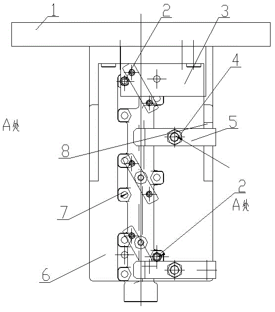
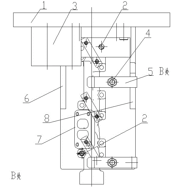
[0022] Embodiment 1: as figure 1 , 2 As shown in .3, a segmented exhaust manifold connection neck processing fixture includes a connection plate 1 and a clamp body 2. The clamp body 2 is fixedly connected with the connection plate 1 in a T-shape by connecting bolts. The clamp body 2. Set a workpiece processing reference plane, on which the front positioning mechanism, the rear positioning mechanism, the front pressing mechanism, the rear pressing mechanism, the front counterweight mechanism and the rear counterweight mechanism are respectively movably connected.

[0023] The front positioning mechanism and the rear positioning mechanism are respectively composed of several positioning pins 2 arranged on the clamp body through positioning holes.

[0024] The front-section pressing mechanism and the rear-section pressing mechanism respectively include a pressing plate 5 and a pressing bolt 4 , and the pressing bolt 4 is movably connected with the clamp body 6 .

[0025] A meth...

Embodiment 2

[0034] Embodiment 2: as figure 1 , 2 As shown in .3, a segmented exhaust manifold connection neck processing fixture includes a connection plate 1 and a clamp body 2. The clamp body 2 is fixedly connected with the connection plate 1 in a T-shape by connecting bolts. The clamp body 2. Set a workpiece processing reference plane, on which the front positioning mechanism, the rear positioning mechanism, the front pressing mechanism, the rear pressing mechanism, the front counterweight mechanism and the rear counterweight mechanism are respectively movably connected.

[0035] The front positioning mechanism and the rear positioning mechanism are respectively composed of several positioning pins 2 arranged on the clamp body through positioning holes.

[0036] The front-section pressing mechanism and the rear-section pressing mechanism respectively include a pressing plate 5 and a pressing bolt 4 , and the pressing bolt 4 is movably connected with the clamp body 6 .

[0037] Pressi...

Embodiment 3

[0047] Embodiment 3: as figure 1 , 2 As shown in .3, a segmented exhaust manifold connection neck processing fixture includes a connection plate 1 and a clamp body 2. The clamp body 2 is fixedly connected with the connection plate 1 in a T-shape by connecting bolts. The clamp body 2. Set a workpiece processing reference plane, on which the front positioning mechanism, the rear positioning mechanism, the front pressing mechanism, the rear pressing mechanism, the front counterweight mechanism and the rear counterweight mechanism are respectively movably connected.

[0048] The front positioning mechanism and the rear positioning mechanism are respectively composed of several positioning pins 2 arranged on the clamp body through positioning holes.

[0049] The front-section pressing mechanism and the rear-section pressing mechanism respectively include a pressing plate 5 and a pressing bolt 4 , and the pressing bolt 4 is movably connected with the clamp body 6 .

[0050] Pressi...


PUM


Abstract

The invention discloses a sectional exhaust manifold connecting neck machining clamp and method. The segmental exhaust manifold connecting neck machining clamp comprises a connecting disc and a clamp body, the clamp body is fixedly connected with the connecting disc in a T-shaped manner through connecting bolts, the clamp body is provided with a workpiece machining reference plane, and a front-section positioning mechanism, a rear-section positioning mechanism, a front-section compressing mechanism, a rear-section compressing mechanism, a front-section weight balance mechanism and a rear-section weight balance mechanism are movably connected on the reference plane respectively. By the sectional exhaust manifold connecting neck machining clamp and method, hard connection of two sections of a sectional exhaust manifold can be realized, and center height tolerance and center height difference generated in the process of machining of the two sections can be avoided.

Description

technical field [0001] The invention belongs to the technical field of machining technology, and in particular relates to a processing fixture and a processing method for a segmented exhaust manifold connection neck. Background technique [0002] At present, the sealing methods of segmented exhaust manifolds in domestic OEMs mostly adopt two structures, one is a conventional structure with two stainless steel sealing rings added, and the other is a hard connection structure without sealing rings. There is a very small assembly gap between the two sections of the product when it is cold, which is convenient for installation in the cold state; when the engine is working, the hot air flowing through the product will expand the very small assembly gap between the two sections of the nozzle to ensure that the product does not leak when it is working At the same time, it can save two stainless steel seals. The advantages of this hard connection structure are: 1. Eliminate two spec...

Claims


Application Information

Patent Timeline
Patent Type & Authority Applications(China)
IPC IPC(8): B23Q3/12B23B1/00
CPCB23B1/00B23Q3/12B23Q2703/10
Inventor 刘建层张银生刘阳
Owner 西峡县内燃机进排气管有限责任公司
Why Eureka
Try Eureka