Surface-Space Managed Network Fabric

Active Publication Date: 2009-06-18
NANT HLDG IP LLC
View PDF24 Cites 37 Cited by
  • Summary
  • Abstract
  • Description
  • Claims
  • Application Information

AI Technical Summary

Benefits of technology

[0016]Spacecraft nodes are located in space (e.g., at altitudes greater than 100 Km) moving relative to a surface of the Earth or substantially stable with respect to positions on the surface. Preferred spacecraft nodes include satellites in geosynchronous orbit. It is also contemplated that spacecraft can be placed in lower or higher orbits as desirable. Furthermore, spacecraft can also be placed at LaGrange points.
[0017]In some embodiments, a surface-space network fabric can i

Problems solved by technology

Unfortunately, satellites generally only provide a “bent-pipe” communication between two ground stations as opposed to integrating into a networked communication system such as the Internet.
Bent-pipe communications suffer from a number of problems, not the least of which is susceptibility to local jamming at a ground station.
If one ground station is unable to send or receive a signal due to jamming, the communication is lost.
Loss of an up/down communication link with a satellite during a military operation, a first response to a disaster, or urgent scenario can cause severe loss of life or can cause substantial financial losses.
Unfortunately, little or no results have yet been announced nor does the contemplated IP network integrate with surface-based fabrics.
Although useful for allowing satellites to commun

Method used


Image

  • Surface-Space Managed Network Fabric
  • Surface-Space Managed Network Fabric
  • Surface-Space Managed Network Fabric

Examples


Embodiment Construction

[0022]Although the following description provides examples of network fabrics having a small number of network nodes, communication links, data channels, or data paths, it should be noted that a fabric can comprise any number of nodes, data links, or data channels.

Network Fabric Overview

[0023]The general concepts of a network fabric as presented herein can be equally applied to a network fabrics located in space or on the surface of the Earth, or other massive body. The term “Earth” is used in this document to mean a massive body and should be interpreted to mean a massive body around which another physical object can orbit. Other massive bodies can include moons, planets, stars (e.g., the Sun), asteroids, comets, or other bodies found in or around a solar system.

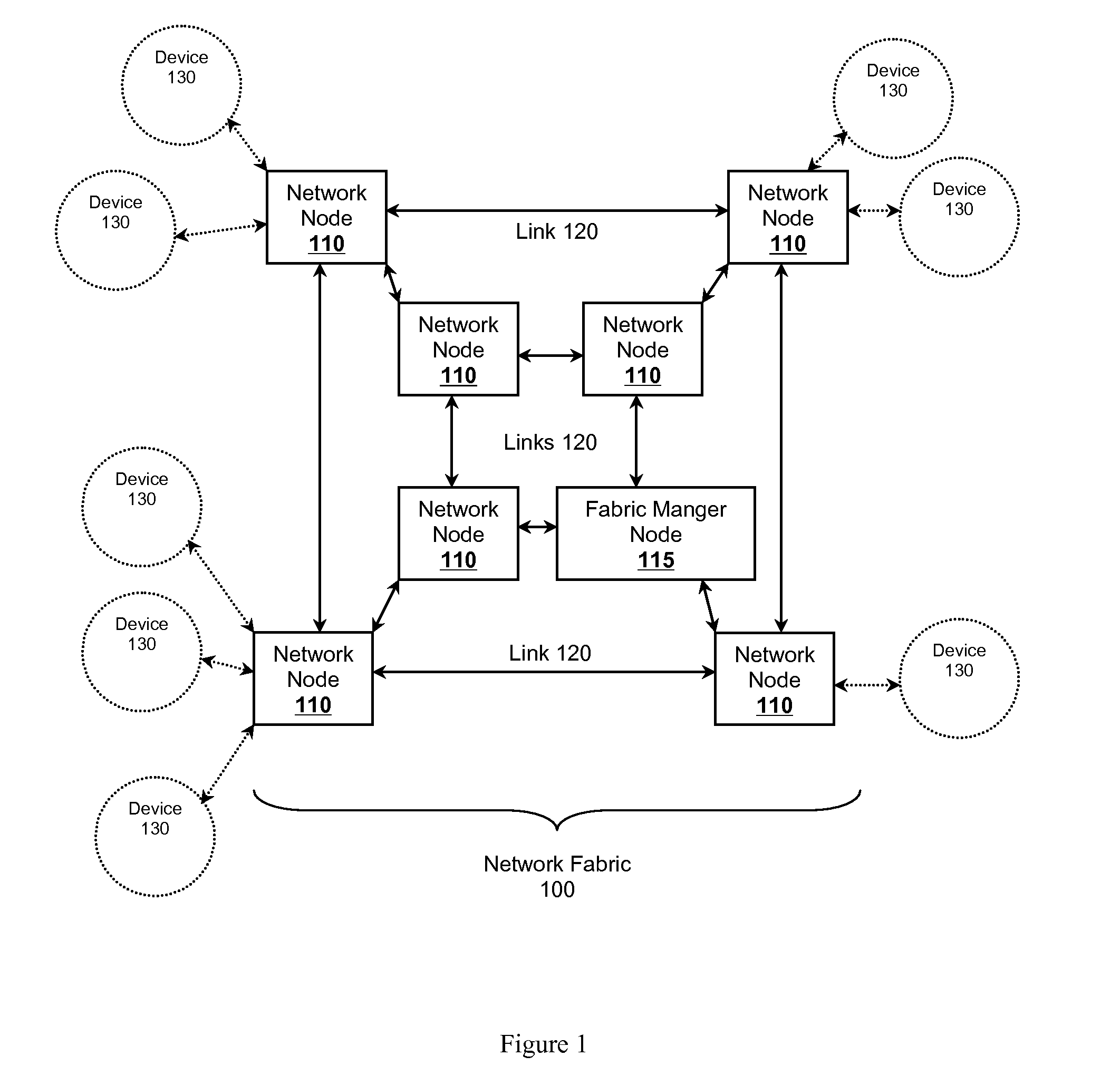
[0024]In FIG. 1 network fabric 100 comprises a plurality of networked nodes 110 interconnected through a plurality of physical communication links 120 connecting neighboring network nodes. In a preferred embodiment, each li...


PUM


Abstract

A managed surface-space network fabric is presented. The surface-space network fabric can include a spaced-based network fabric and a surface-based network fabric integrated together to form a single fabric managed by a global fabric manager. The global fabric manager cooperates with other fabric managers local to each fabric to establish a communication topology among all the nodes of the fabric. Preferred topologies include paths from any port on a node to any other port on another node in the fabric. The surface-space fabric, and each individual fabric, can function as a distributed core fabric operating as a single, coherent device.

Description

[0001]This application claims priority to U.S. provisional application having Ser. No. 61 / 079,892 filed on Jul. 11, 2008; and this application is a continuation-in-part of U.S. patent application having Ser. No. 12 / 120,024 filed on May 13, 2008, which claims priority to U.S. provisional application having Ser. No. 61 / 013,852 filed Dec. 14, 2007, U.S. provisional applications having Ser. Nos. 61 / 014,306 and 61 / 014,367 filed on Dec. 17, 2007, U.S. provisional application having Ser. No. 61 / 023,004 filed on Jan. 23, 2008, and U.S. provisional application having Ser. No. 61 / 024,842 filed on Jan. 30, 2008. These and all other extrinsic materials discussed herein are incorporated by reference in their entirety. Where a definition or use of a term in an incorporated reference is inconsistent or contrary to the definition of that term provided herein, the definition of that term provided herein applies and the definition of that term in the reference does not apply.FIELD OF THE INVENTION[00...

Claims


Application Information

Patent Timeline
IPC IPC(8): H04B7/185
CPCH04B7/19H04B7/18584H04B7/1856H04W76/04H04L41/042H04B7/18504H04W84/06H04L41/12H04W76/20H04W36/12H04W76/25H04W36/18H04W36/24
Inventor WITTENSCHLAEGER, THOMAS
Owner NANT HLDG IP LLC
Why Eureka
Try Eureka