Method of designing a multistage turbine for a turbomachine

Active Publication Date: 2009-06-18
SN DETUDE & DE CONSTR DE MOTEURS DAVIATION S N E C M A
View PDF2 Cites 18 Cited by
  • Summary
  • Abstract
  • Description
  • Claims
  • Application Information

AI Technical Summary

Benefits of technology

[0007]A particular object of the invention is to provide a solut

Problems solved by technology

Nevertheless, those methods make use of complex calculations that are very expensive in terms of time, thereby making them incompatible with conventional design deadlines.
Furthermore, those methods do not always take account of multistage aerodynamic coupling over the full height of the turbine flow section, i.e. over the entire radial extent of the airfoils of the rows.
This approach presents a major drawback: the pairs of rows are positioned angularly independ

Method used


Image

  • Method of designing a multistage turbine for a turbomachine
  • Method of designing a multistage turbine for a turbomachine
  • Method of designing a multistage turbine for a turbomachine

Examples


Example

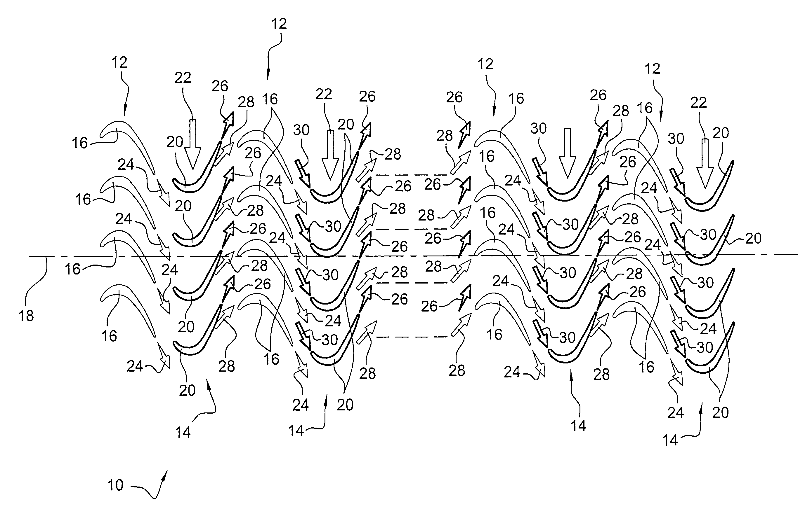
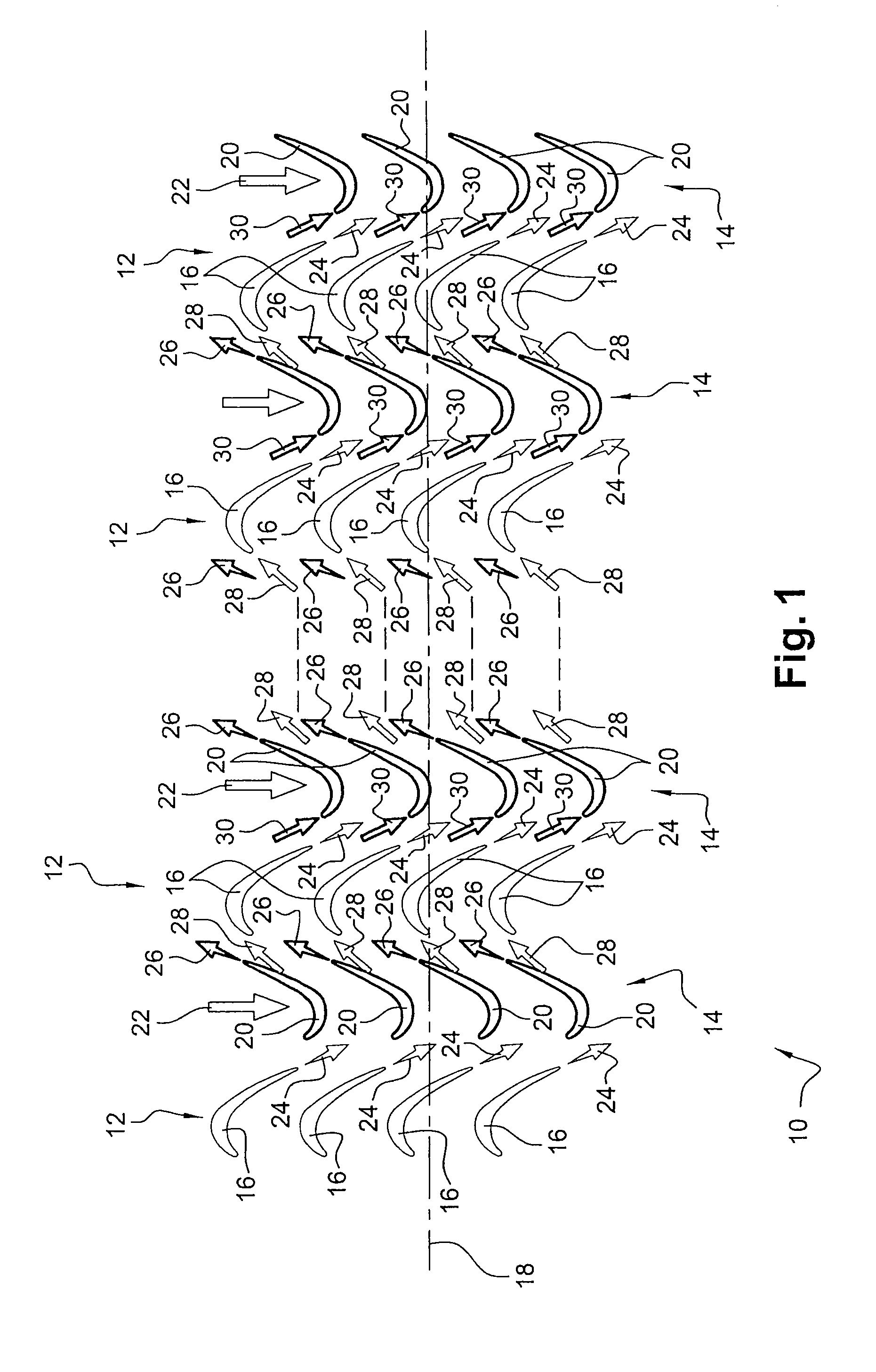
[0045]Reference is made initially to FIG. 1 which shows in highly diagrammatic manner a portion of a multistage turbine 10 of a turbomachine such as an airplane turboprop or turbojet, the turbine 10 having a finite number k of stages, each comprising a stator row or grid 12 and a rotor row or grid 14 situated downstream from the stator row 12.

[0046]Each stator row 12 comprises a plurality of vanes 16 that are regularly distributed around the longitudinal axis 18 of the turbine and that are carried by an outer casing of the turbine (not shown). Each rotor row 14 comprises a plurality of blades 20 that are carried by a disk (not shown) and that are likewise regularly distributed around the axis 18 of the turbine.

[0047]The stator and rotor rows 12 and 14 have the same number of airfoils 16 and 20. In a variant, the number of airfoils 16, 20 in one row 12, 14 may be a multiple of the number of airfoils in a row of the same type situated upstream therefrom. Rows of a given type may there...


PUM


Abstract

A method of designing a multistage turbine for a turbomachine in which each turbine stage comprises a stator row and a rotor row each made up of an annular row of airfoils, wherein, for all of the stator or rotor rows, it consists in simultaneously modifying the shapes of the airfoils of said rows to straighten out the wakes from the trailing edges of said airfoils, then in angularly positioning the rows in such a manner that the wakes from the airfoils of the stator (or rotor) airfoils impact against the leading edges of the stator (or rotor, respectively) airfoils of the rows situated downstream, in order to achieve multistage aerodynamic coupling simultaneously over the turbine as a whole.

Description

FIELD OF THE INVENTION [0001]The present invention relates to a method of designing a multistage turbine for a turbomachine such as an airplane turboprop or turbojet.BACKGROUND OF THE INVENTION [0002]A turbomachine turbine comprises a plurality of stages, each made up of a stationary stator grid or row and a moving rotor grid or row. Each row is made up of an annular row of airfoils that are regularly distributed around the longitudinal axis of the turbine. The airfoils of a rotor row are carried by a disk connected to the shaft of the turbine, and the airfoils of a stator row are connected to an outer casing of the turbine.[0003]The airfoils of the rows extend substantially across the entire radial extent of the flow section in which hot gas flows through the turbine. The hot gas leaves the combustion chamber of the turbomachine and flows through the turbine, thereby delivering energy to the rotor rows that drive the turbine shaft in rotation.[0004]In order to improve the performan...

Claims


Application Information

Patent Timeline
IPC IPC(8): F01D1/02F01D9/04F01D5/14
CPCF01D5/141Y02T50/673F01D9/041F01D5/142Y02T50/60
Inventor GUIMBARD, JEAN-MICHEL BERNARDKUENY, OLIVIERSCHWARTZ, ERIC
Owner SN DETUDE & DE CONSTR DE MOTEURS DAVIATION S N E C M A
Why Eureka
Try Eureka