Blood pressure motion sensing

a motion sensing and blood pressure technology, applied in the field of blood pressure monitoring, can solve the problems of significant blood pressure measurement error, clinician distraction, and inability to realize the blood pressure measurement has been corrupted, and achieve the effect of reducing the movement of the limb

Inactive Publication Date: 2009-06-18
WELCH ALLYN INC
View PDF17 Cites 44 Cited by
  • Summary
  • Abstract
  • Description
  • Claims
  • Application Information

AI Technical Summary

Benefits of technology

[0026]In another aspect, the invention features a method for detecting a motion artifact in a non-invasive blood pressure measurement comprising the steps of: providing a blood pressure cuff having at least one bladder, providing a blood pressure monitor pneumatically coupled to the blood pressure cuff, providing at least one accelerometer mechanically disposed such that the at least one accelerometer substantially measures a motion of the at least one bladder, attaching the blood pressure cuff to a person, performing an oscillometric procedure using the blood pressure cuff, measuring a pressure and a motion of the at least one bladder during the oscillometric procedure, determining an effect of the motion on the non-invasive blood pressure measurem

Problems solved by technology

However, if the limb to which the blood pressure cuff is affixed is in motion during the blood pressure cuff bladder deflation, the pressure sensor can respond to additional motion induced pressure artifacts.
In many cases the magnitude of the motion can cause significant error in the blood pressure measurement results.
In some cases, particularly where the NIBP measurement equipment is fully automatic, a clinician might be distracted and not realize that a bloo

Method used


Image

  • Blood pressure motion sensing
  • Blood pressure motion sensing
  • Blood pressure motion sensing

Examples


Embodiment Construction

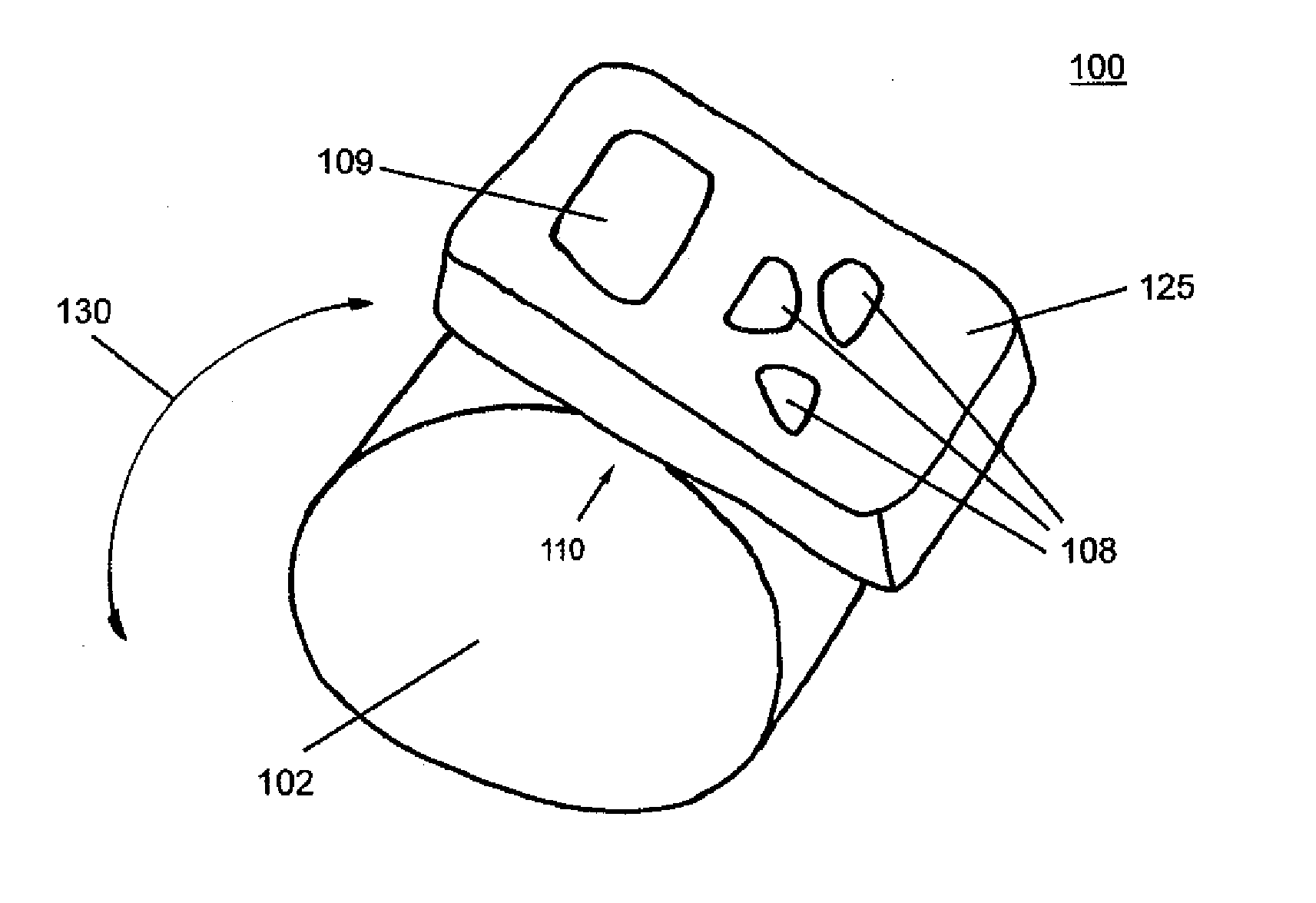
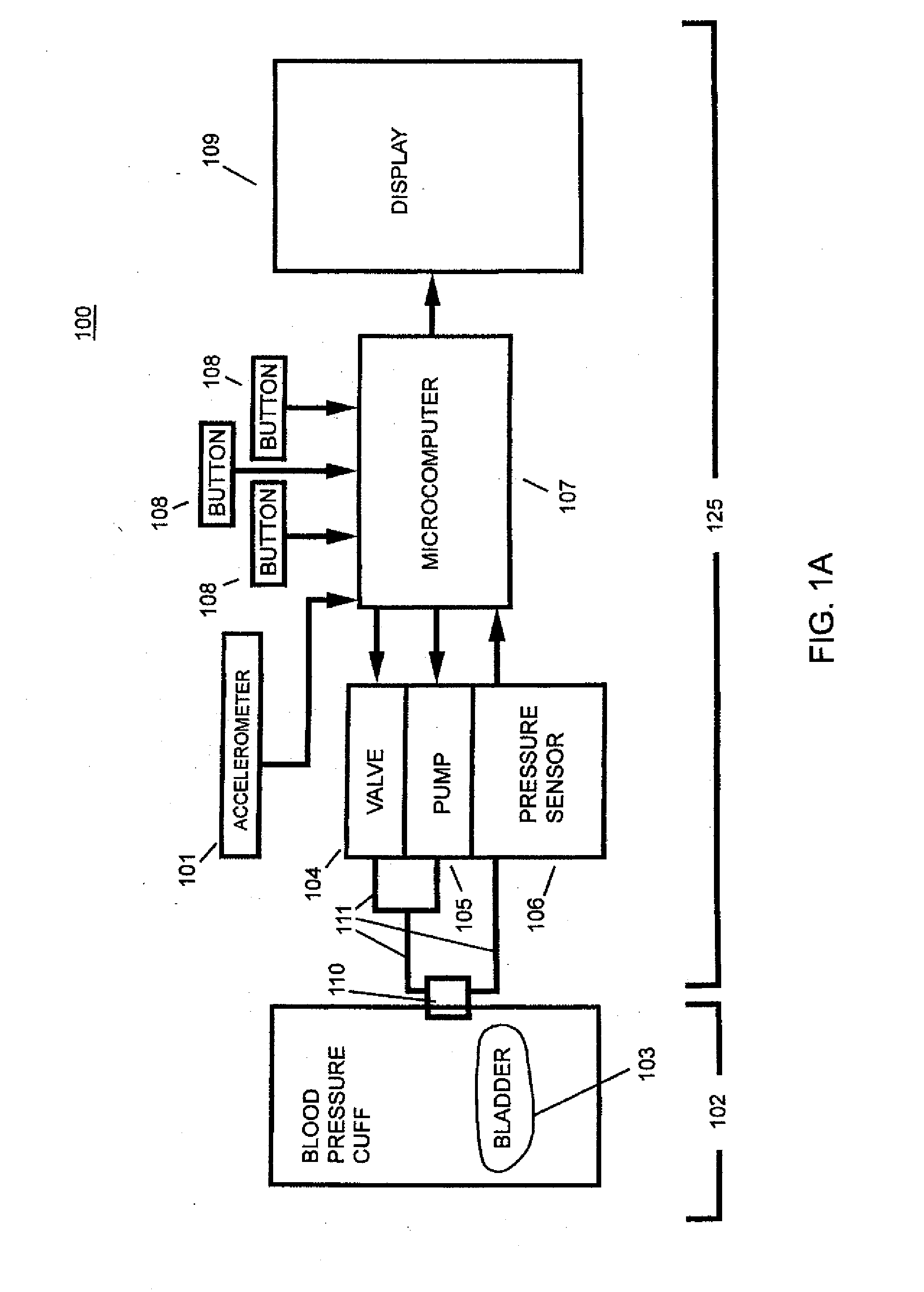
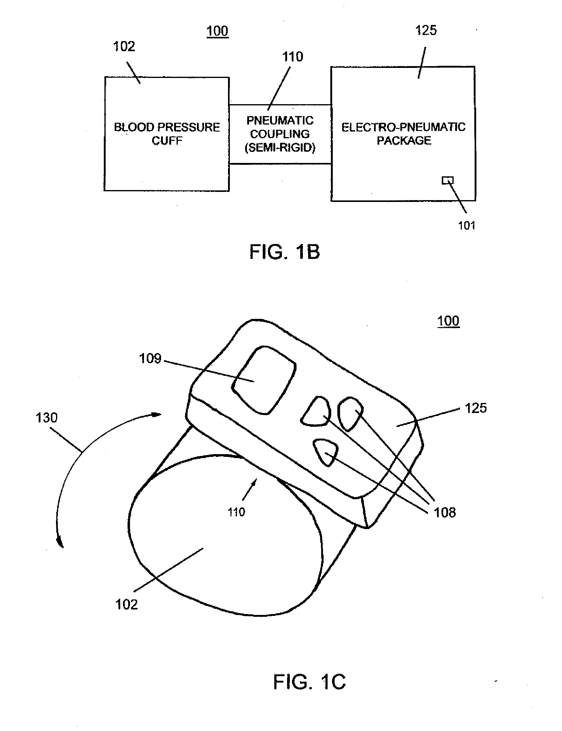
[0048]FIG. 1A shows a block diagram of an exemplary embodiment of a blood pressure monitor 100 according to the invention. Accelerometer 101 can be situated on or in an electro-pneumatic package 125 such that it is mechanically coupled to the monitor in such a way that the accelerometer signal substantially reflects any acceleration of blood pressure cuff 102. Blood pressure cuff 102 can include at least one bladder 103. A microcomputer 107 can run an algorithm, typically present as firmware, that controls the various electromechanical components of the blood pressure monitor, processes information, and also typically receives analog and / or digital inputs from electrical signals from sensors, and to display calculated blood pressure information on a display such as display 109.

[0049]A blood pressure monitor 100 according to the invention can provide information indicative of a patient's activity level as measured by the one or more accelerometers 101. Such information can be for use...


PUM


Abstract

The invention relates to a blood pressure monitor for measuring the blood pressure of a person including a blood pressure cuff. The blood pressure monitor also includes an electro-pneumatic package. The electro-pneumatic package includes a pump, a valve, a pressure sensor, and one or more accelerometers. A pneumatic mechanical coupling is configured to pneumatically and mechanically directly couple the blood pressure cuff to the electro-pneumatic package, wherein a signal from the one or more accelerometers configured to indicate an activity level of the person during a blood pressure measurement. A display is configured to display an indication of the activity level. The invention also relates to a blood pressure monitor wherein an electronics circuit is configured to receive the motion signal from the one or more accelerometers during a blood pressure measurement. The invention also relates to a method for detecting a motion artifact in a non-invasive blood pressure measurement.

Description

FIELD OF THE INVENTION [0001]This invention relates generally to blood pressure monitoring and more particularly to blood pressure monitoring apparatus including motion artifact sensing.BACKGROUND OF THE INVENTION [0002]Non-invasive blood pressure (NIBP) monitors typically use a blood pressure cuff. To measure a person's blood pressure, a blood pressure cuff of an appropriate size can be affixed to a person's limb, typically to the upper portion of an adult's arm or to an infant's leg. The blood pressure cuff generally includes at least one inflatable bladder. Blood pressure measurements are made by inflating the bladder and then monitoring the pressure of the bladder using a pressure sensor as the bladder is deflated. Because the person's heart is pumping blood through arteries in the limb constrained by the blood pressure cuff, the bladder pressure measured by the pressure sensor includes pressure changes caused by pumping blood superimposed on the changing bladder pressure.[0003]...

Claims


Application Information

Patent Timeline
IPC IPC(8): A61B5/022
CPCA61B5/022A61B5/02225A61B2562/0219A61B5/721A61B5/11
Inventor LANE, JOHN A.WHITAKER, TYSON B.KINSLEY, MATTHEW J.MARTIN, SCOTT A.GRANT, THOMAS J.MEYER, STEPHEN F.
Owner WELCH ALLYN INC
Why Eureka
Try Eureka