Method and apparatus for moving a swing tail cargo door on an aircraft

a technology of swing tail and cargo door, which is applied in the field of aircraft, can solve the problems of manual labor, equipment may place unnecessary stress on the swing tail cargo door, and cannot be quickly closed,

Inactive Publication Date: 2009-06-18
THE BOEING CO
View PDF22 Cites 17 Cited by
  • Summary
  • Abstract
  • Description
  • Claims
  • Application Information

AI Technical Summary

Benefits of technology

[0009]The advantageous embodiments provide a computer implemented method, apparatus, and computer usable program code for a mobile tail support control system. In an advantageous embodiment, a mobile tail support control system controls movement of a mobile tail support apparatus. The control system comprises a data processing system, an output device, a set of load sensors, a set of position sensors, and a computer program product executing on a data processing system. The output device is capable of generating signals for managing movement of a mobile tail support apparatus. The set of load sensors are coupled to the data processing system and are capable of detecting a set of loads associated with a swing tail cargo door. The set of load sensors comprise a first load sensor capable of detecting a tangential load of the swing tail cargo door and a second load sensor capable of detecting a vertical load of the swing tail cargo door. The set of position sensors are coupled to the data processing system and capable of detecting a position of the mobile tail support apparatus relative to the swing tail cargo door. The set of position sensors comprise a first position sensor capable of detecting an angle of the mobile tail support apparatus relative to the swing tail cargo door when the mobile tail support apparatus is coupled to the swing tail cargo door, a second position sensor capable of detecting a radial displacement from a fixed distance from a centerline of a hinge for the swing tail cargo door to a centerline for a ball fitting of the mobile tail support apparatus relative to the swing tail cargo door, and a third position sensor capable of detecting a steering angle of a wheel on the mobile tail support apparatus. The computer program product executing on the data processing system is capable of receiving information from the set of load sensors and the set of position sensors and is capable of generating signals to manage the mobile tail support apparatus. In executing the computer program product, the data processing system generates a signal to halt the movement of the mobile tail support apparatus if the radial displacement exceeds a threshold distance and the data processing system generates a set of steering signals based on the angle of the mobile tail support apparatus relative to the swing tail cargo door and the radial displacement in which a set of steering signals are displayed to an operator of the mobile tail support apparatus or automatically control a direction of travel of the mobile tail support apparatus.

Problems solved by technology

These types of processes may be manually intensive requiring equipment and personnel to move and align the swing tail cargo door during repositioning or the opening or closing of a swing tail cargo door.
Currently used systems, however, may not allow for quick closure especially in high wind conditions.
Additionally, currently used techniques and equipment may place unnecessary stress on the swing tail cargo door during movement or loading operations and unloading operations of the swing tail cargo door.
Currently used techniques also may add weight to the aircraft if a door control / support mechanism / system is built into the plane.
In selectively changing the movement, a determination is made as to whether continued movement of the mobile tail support apparatus in the current direction would cause an undesired load on the swing tail cargo door during opening and closing operations.

Method used


Image

  • Method and apparatus for moving a swing tail cargo door on an aircraft
  • Method and apparatus for moving a swing tail cargo door on an aircraft
  • Method and apparatus for moving a swing tail cargo door on an aircraft

Examples


Embodiment Construction

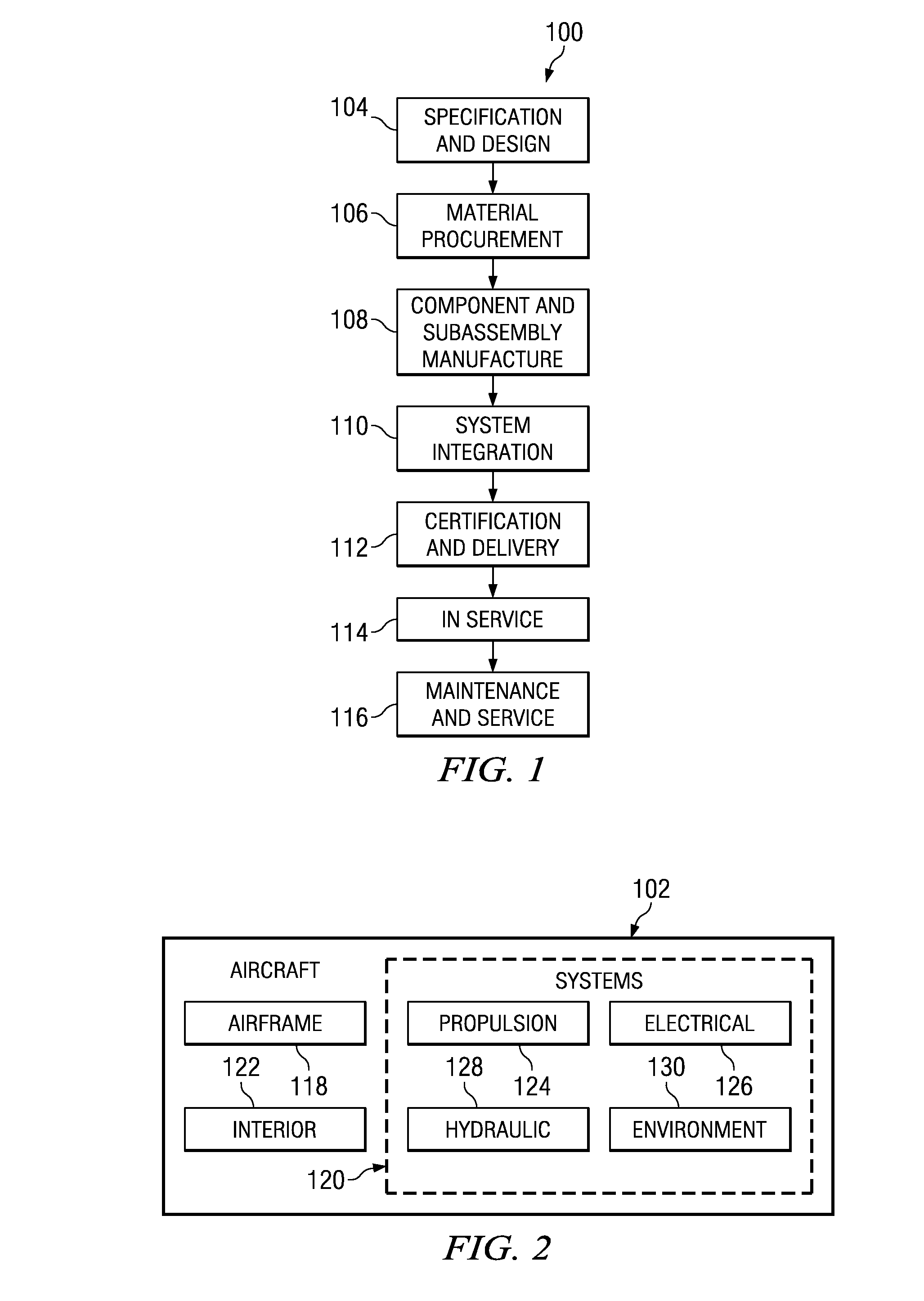
[0034]Referring more particularly to the drawings, embodiments of the disclosure may be described in the context of an aircraft manufacturing and service method 100 as shown in FIG. 1 and an aircraft 102 as shown in FIG. 2. During pre-production, exemplary method 100 may include specification and design 104 of the aircraft 102 and material procurement 106. During production, component and subassembly manufacturing 108 and system integration 110 of the aircraft 102 takes place. Thereafter, the aircraft 102 may go through certification and delivery 112 in order to be placed in service 114. While in service by a customer, the aircraft 102 is scheduled for routine maintenance and service 116 (which may also include modification, reconfiguration, refurbishment, and so on).

[0035]Each of the processes of method 100 may be performed or carried out by a system integrator, a third party, and / or an operator (e.g., a customer). For the purposes of this description, a system integrator may inclu...


PUM


Abstract

A computer implemented method, apparatus, and computer usable program code for a mobile tail support control system. An apparatus comprises a data processing system, an output device, a set of load sensors, a set of position sensors, and a computer program product executing on the data processing system. The output device is capable of generating signals for managing movement of a mobile tail support apparatus. The set of load sensors may be coupled to the data processing system and may be capable of detecting loads associated with a swing tail cargo door. The set of position sensors are coupled to the data processing system and detect a position of the mobile tail support apparatus relative to the swing tail cargo door. The computer program product may receive information from the set of load sensors and the set of position sensors and generate signals to manage the mobile tail support apparatus.

Description

BACKGROUND INFORMATION[0001]1. Field[0002]The present disclosure relates generally to an improved aircraft and in particular to a swing tail cargo door on an aircraft. Still more particularly, the present disclosure relates to a method and apparatus for moving a swing tail cargo door on an aircraft.[0003]2. Background[0004]A swing tail aircraft may be an aircraft in which the tail portion of the aircraft may be moveably mounted to allow the tail portion to swing or move to expose the inner portion of the aircraft. This tail may also be referred to as a swing tail cargo door.[0005]With the use of the swing tail cargo door, larger cargo, such as, without limitation, vehicles, fuselage sections, or wings, may be placed into and moved out of an aircraft. This type of cargo may be loaded and unloaded from the back of the aircraft with the swing tail in an open position. In this manner, much larger parts may be placed into the aircraft in comparison to other types of cargo doors.[0006]Wit...

Claims


Application Information

Patent Timeline
Patent Type & Authority Applications(United States)
IPC IPC(8): G06F17/00
CPCB64F1/22B64C1/22B60P3/00B60S13/00B62D6/00B64C1/1415B64F1/00
Inventor STEBBINS, ROBIN WILLIAMKAUFFMAN, BRAD ALANKRAFT, KURT RANDALLVYESON, CRAIG ALAN
Owner THE BOEING CO
Why Eureka
Try Eureka