

Method System and Device for Generation of a Pseudo-Random Data Sequence
- Summary
- Abstract
- Description
- Claims
- Application Information
AI Technical Summary
Benefits of technology
Problems solved by technology
Method used
Image

Examples
first embodiment
[0110]The series of operations of the first embodiment can be defined as follows:[0111]set as the only shifting rule of the first set of rules R1 the rule r1,1=“shift one bit to the right”;[0112]set as updating rules of the second set of rules R2 the following rules:
[0113]r2,1=“place the bit from the window pointed to by pf1 in E”;
[0114]r2,2=“if the content of the window pointed to by pf2 is a pattern from E, then update s←b”;
[0115]r2,3=“if the content of the window pointed to by pf2 is not a pattern from E, then update s←b⊖1”;[0116]set as the third set of rules R3 the following rules:
[0117]r3,1=“as long as the content of the window pointed to by pf2 is not a pattern from E, shift the window pointed by pf2 according to the rule r1,1”;
[0118]r3,2=“shift the windows pointed to by pf1 and pf2 according to the rule r1,1”;[0119]apply the rules r2,1, r2,2, r2,3, r3,1 and r3,2 in that order; and[0120]output the output pattern s.
[0121]The FIG. 3 flowchart shows the execution of the above ser...
second embodiment
[0133]FIG. 4 is a flowchart showing the execution of the series of operations of a
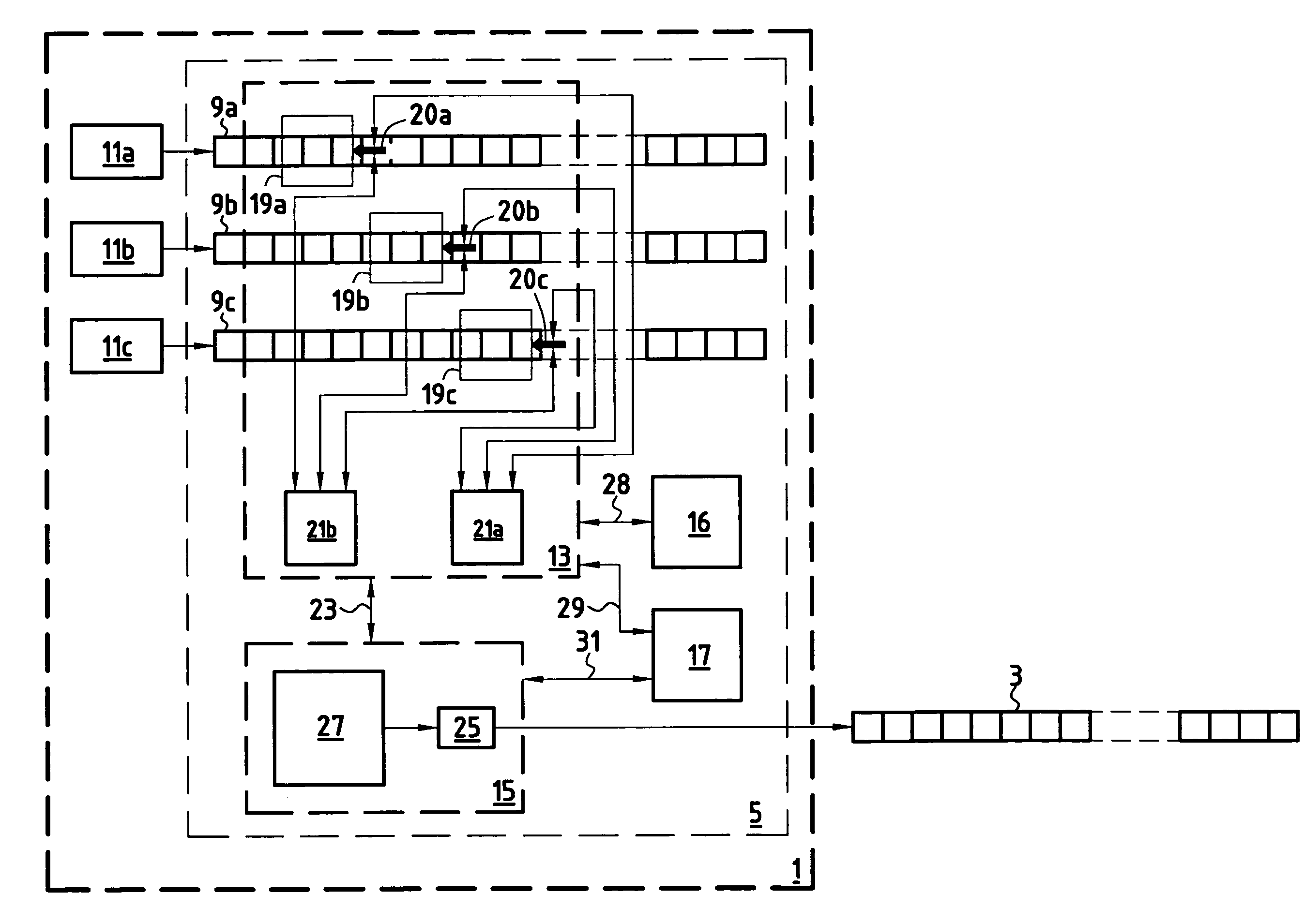
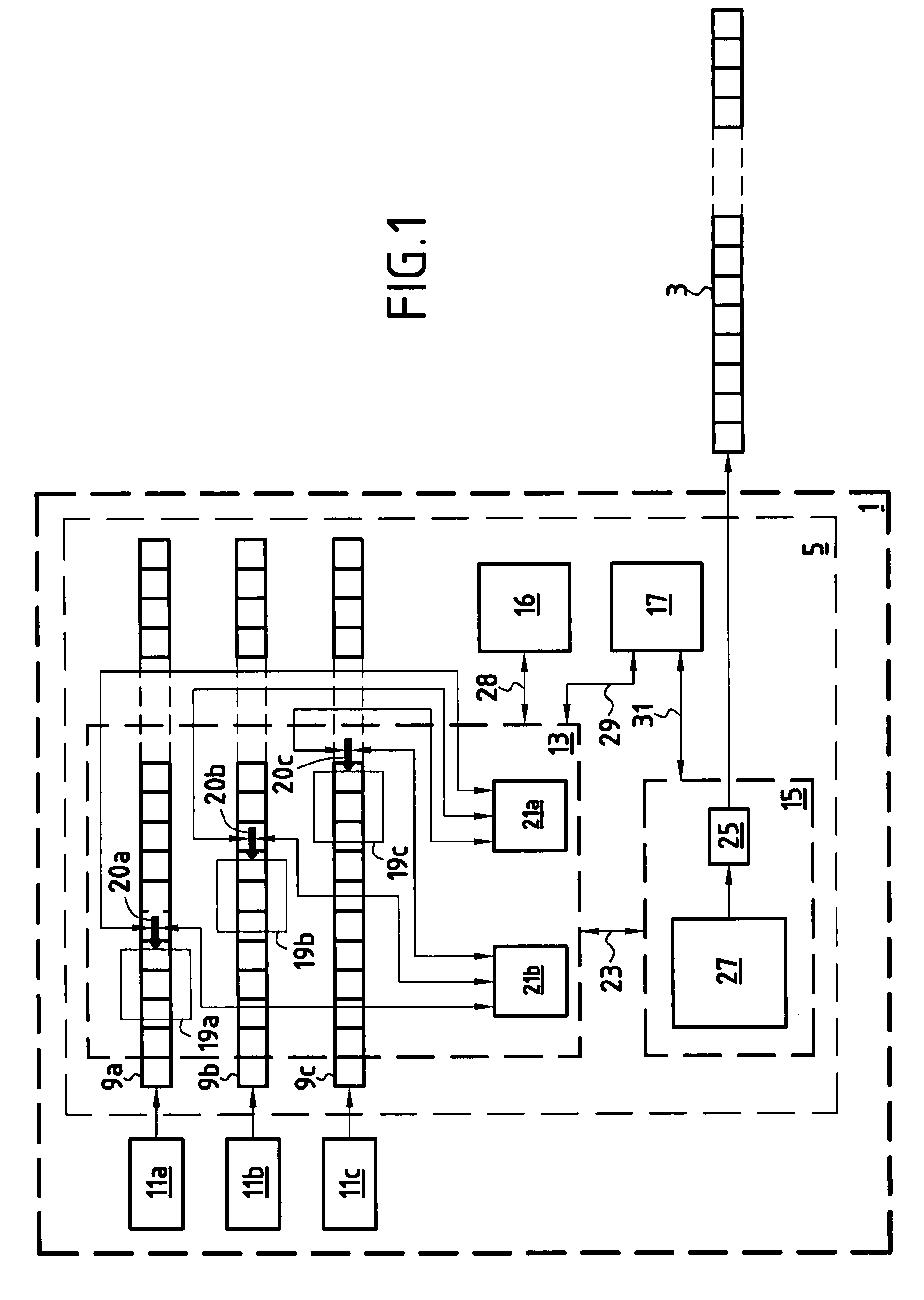
[0134]This second embodiment includes three initial data sequences 9a, 9b and 9c and three windows 19a, 19b and 19c of length “1”. The window 19a is shifted over the sequence 9a, the window 19b is shifted over the sequence 9b, and the window 19c is shifted over the sequence 9c. Each of the three windows is initially positioned over the first bit of the associated data sequence.
[0135]Three pointers 20a, 20b, 20c numbered pf1, pf2 and pf3 to the windows 19a, 19b and 19c are defined. At initialization time, pf1 points to the window 19a, pf2 points to the window 19b, and pf3 points to the window 19c. A fourth pointer numbered pftemp is defined for temporarily storing the value of pf1 during modifications of the values of pf1, pf2 and pf3. The set E of search patterns is initialized to the empty set before each execution of the series of operations or mechanism of the method.
[0136]The mechanism or series of...
third embodiment
[0155]FIG. 5 is a flowchart showing the execution of the series of operations of a
[0156]This third embodiment comprises two initial data sequences 9a, 9b and two windows 19a and 19b. The window 19a is shifted over the sequences 9a and the window 19b is shifted over the sequences 9b. Each window is initially fixed over the first bit of the associated sequence. Two pointers 20a and 20b numbered pf1 and pf2 to the windows 19a, 19b are defined. At initialization, pf1 points to the window 19a and pf2 points to the window 19b.
[0157]The mechanism or series of operations of the third embodiment can be defined as follows:[0158]there is set as the only shifting rule of the first set of rules R1 the rule r1,1=“shift one bit to the right”;[0159]there are set as updating rules of the second set of rules R2 the rules:
[0160]r2,1=“place the bit from the window pointed to by pf1 in E”;
[0161]r2,2=“assign to s the value of the bit from the window pointed to by pf1”;
[0162]r2,3=“exchange the values of ...
PUM
 Abstract
Description
Claims
Application Information