

Recording control apparatus, recording control method, and computer program product
a recording control and control apparatus technology, applied in the direction of electrical apparatus construction details, instruments, memory systems, etc., can solve the problems of inability to detect the wrong position of the nvram device, the access to the incorrect nvram device, and the loss or rewriting of important user information stored in the nvram devi
- Summary
- Abstract
- Description
- Claims
- Application Information
AI Technical Summary
Benefits of technology
Problems solved by technology
Method used
Image

Examples
first embodiment
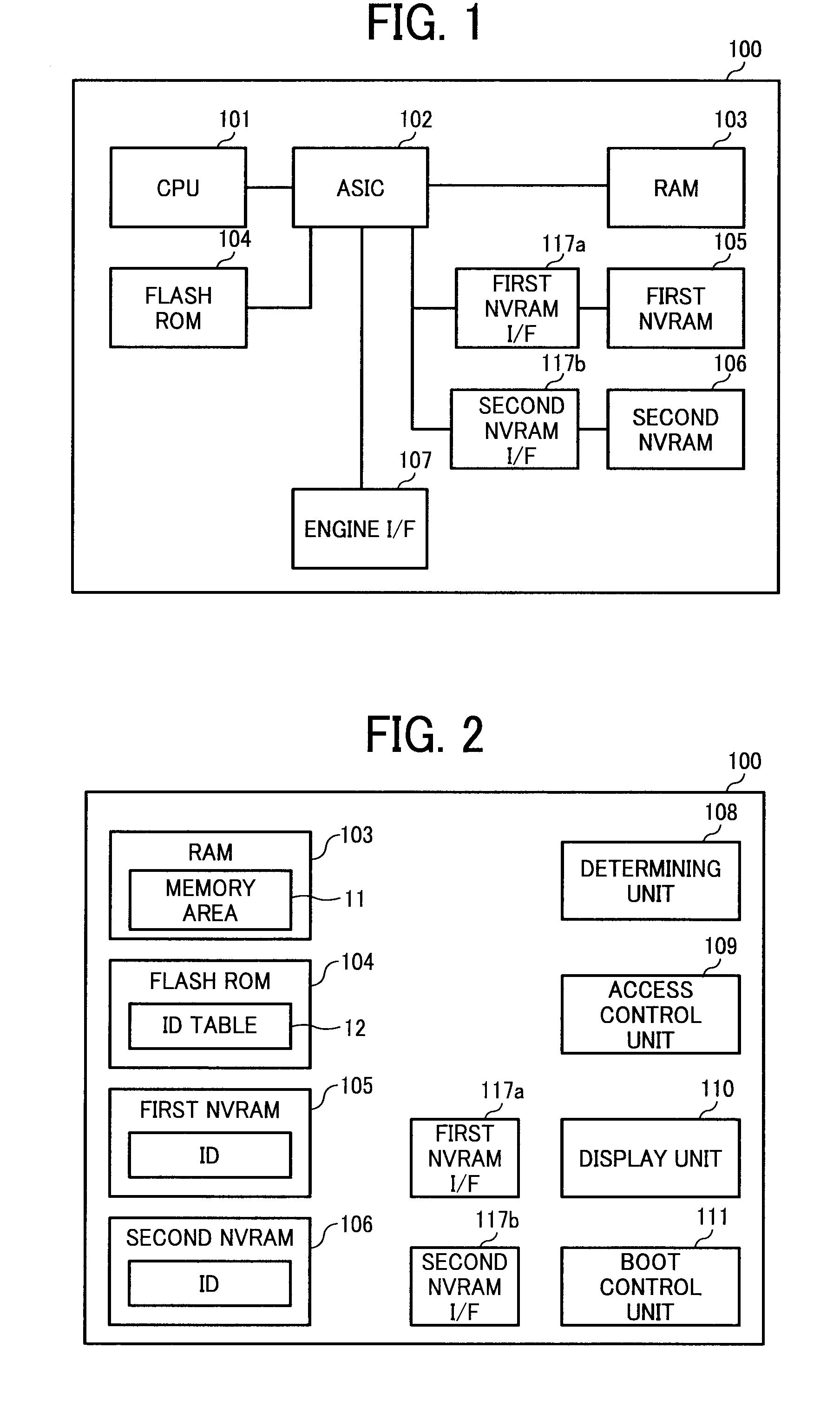
[0035]FIG. 1 is a block diagram of a hardware configuration of a recording control apparatus 100 according to the present invention. The recording control apparatus 100 includes a central processing unit (CPU) 101, an application specific integrated circuit (ASIC) 102, a random access memory (RAM) 103, a flash read-only memory (ROM) 104, a first NVRAM 105, a second NVRAM 106, a first NVRAM interface (I / F) 117a, a second NVRAM I / F 117b, and an engine I / F 107.
[0036]In the present embodiment, the recording control apparatus 100 is installed in an image forming apparatus. However, the present invention is not limited to the image forming apparatus. The recording control apparatus 100 can be applied to any apparatuses as long as the apparatuses include a memory. Incidentally, the image forming apparatus means any of a copier, a scanner, a facsimile machine, a printer, and an MFP.
[0037]The ASIC 102 controls buses connecting among devices included in the recording control apparatus 100 and...
second embodiment
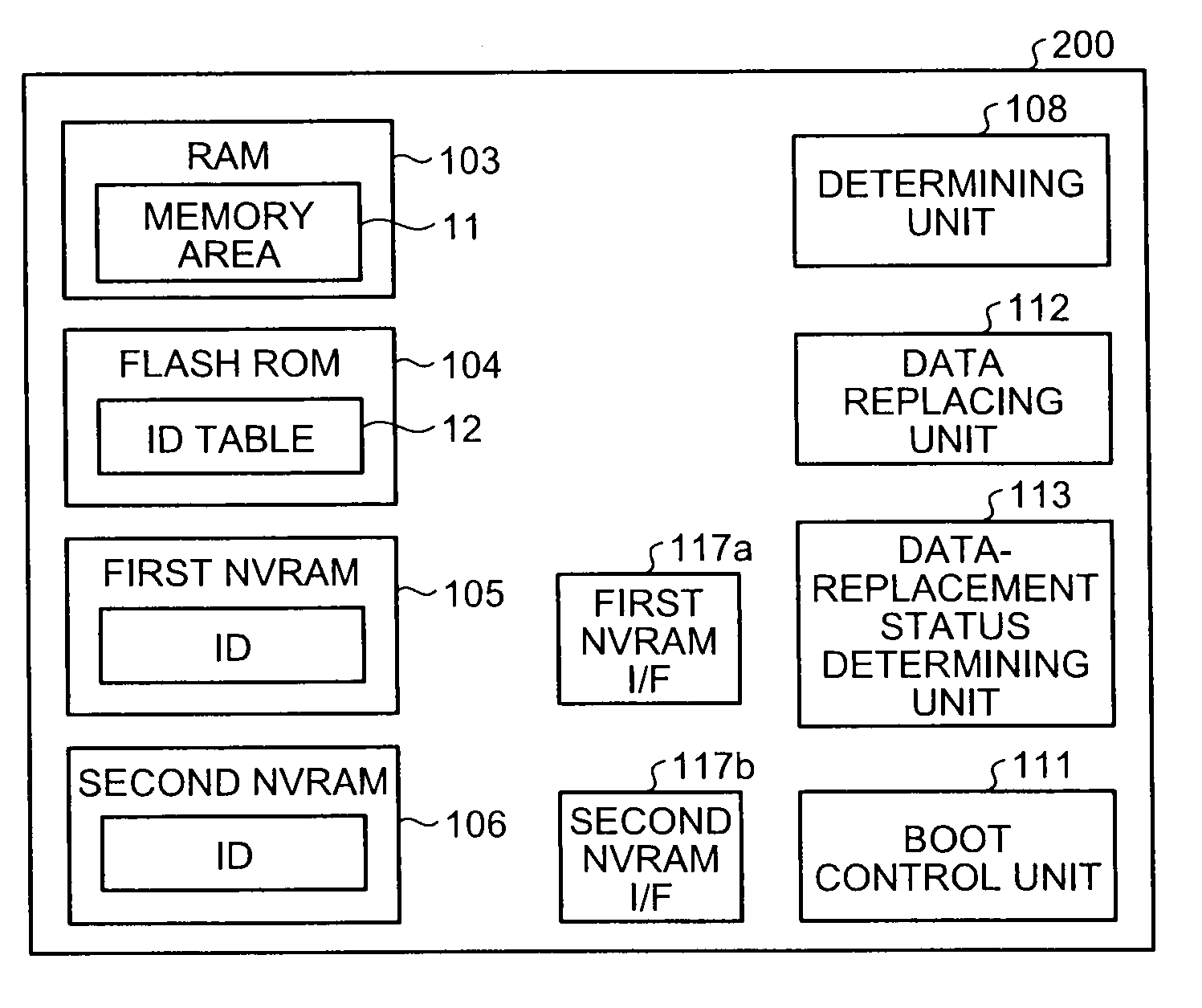
[0068]FIG. 5 is a functional block diagram of a recording control apparatus 200 according to the present invention. The recording control apparatus 200 includes the determining unit 108, a data replacing unit 112, a data-replacement status determining unit 113, the boot control unit 111, the RAM 103, the flash ROM 104, the first NVRAM 105, the second NVRAM 106, the first NVRAM I / F 117a, and the second NVRAM I / F 117b. The portions identical to those in FIG. 2 are denoted with the same reference numerals, and the description of those portions is omitted. Furthermore, a hardware configuration of the recording control apparatus 200 is identical to that of the recording control apparatus 100 shown in FIG. 1, and the description of the hardware configuration of the recording control apparatus 200 is omitted.
[0069]The data replacing unit 112 replaces data stored in the first and second NVRAMs 105 and 106 by that is stored in the other NVRAM when the determining unit 108 determines that the...
third embodiment
[0095]FIG. 8 is a functional block diagram of a recording control apparatus 300 according to the present invention. The recording control apparatus 300 includes a determining unit 308, an ID-table managing unit 114, the boot control unit 111, the RAM 103, the flash ROM 104, the first NVRAM 105, the second NVRAM 106, the first NVRAM I / F 117a, and the second NVRAM I / F 117b. The portions identical to those in FIG. 2 are denoted with the same reference numerals, and the description of those portions is omitted. Furthermore, a hardware configuration of the recording control apparatus 300 is identical to that of the recording control apparatus 100 shown in FIG. 1, and the description of the hardware configuration of the recording control apparatus 300 is omitted.
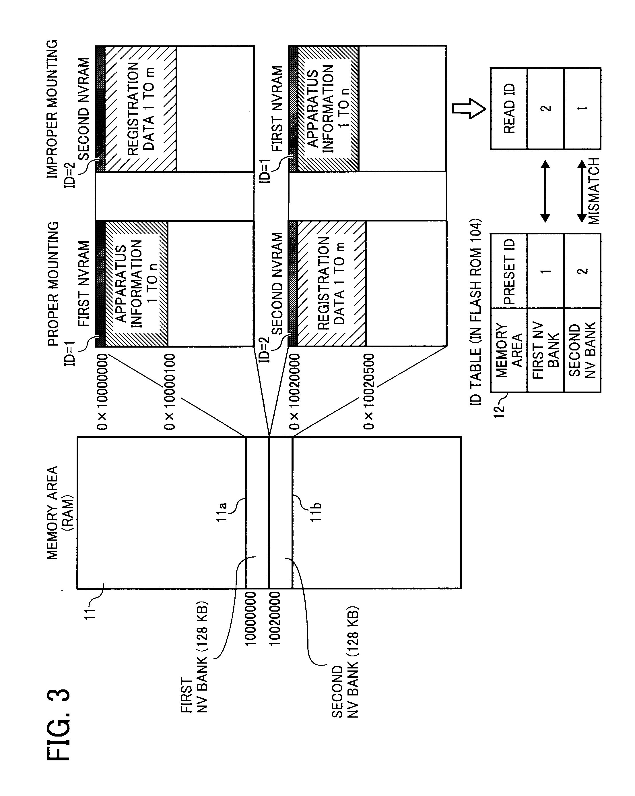
[0096]The determining unit 308 determines whether the first and second NVRAMs 105 and 106 are mounted in the right positions on the control board, i.e., are attached to the first and second NVRAM I / Fs 117a and 117b respectively by...
PUM
 Abstract
Description
Claims
Application Information