Ball seat having segmented arcuate ball support member

a ball support member and ball seat technology, applied in the field of ball seats, can solve the problems of plastic balls that have limited compressive strength, plastic balls that fail, etc., and achieve the effect of reducing the likelihood that the force on the ball will push the ball through the seat, reducing the likelihood of the ball pushing through the seat, and increasing the pressur

Active Publication Date: 2009-06-25
BAKER HUGHES INC
View PDF17 Cites 217 Cited by
  • Summary
  • Abstract
  • Description
  • Claims
  • Application Information

AI Technical Summary

Benefits of technology

[0010]Broadly, ball seats having a housing, a seat, and a plug element such as a ball are disclosed. Typically, the ball is landed and the conduit is pressurized to a predetermined pressure. Upon pressurization of the conduit so that the ball is pushed into the seat, the plug element support member extends from its retracted position, i.e., the position in which the plug element support member is not touching or otherwise in engagement with the ball, and into the bore of the ball seat to engage with, and provide additional support to, the ball as it is being pressurized. In other words, the force of the ball into the seat by the pressure in the tubing causes the seat to move the plug element support member inward into the bore of the ball seat from its retracted position toward the centerline (or axis) of the bore of the ball seat and into its extended positions, thus either making contact with the previously unsupported area of the ball or otherwise distributing the force acting on the ball over a larger surface area so that the ball and seat can withstand higher pressures and / or restrict movement of the ball through the seat inner diameter as the pressure begins to deform and extrude the ball through the seat.
[0011]By making contact with, or engaging, the ball, the plug element support members provide support for the ball because the resulting force against the ball caused by pressurization of the ball against the seat is spread out between the existing seat contact area and the additional contact area provided by the extended plug element support member. As the pressure is increased, the force on the ball is transferred to both the original seal area of the seat and to the plug element support member. The applied pressure to the plug element support member, therefore, decreases the likelihood that the force on the ball will push the ball through the seat.
[0012]Due to the plug element support member providing additional support to the ball, the ball seats disclosed herein provide a plugging method where higher pressure can be exerted onto a seat by a lower strength ball without exceeding the ball's bearing or load strength. Further, the contact pressure resulting from having additional contact area provided by the plug element support members will be effectively reduced without affecting the sealability of the ball. Thus, more sizes of balls in closer increments can be utilized in various applications such as in frac ball systems. Additionally, more balls can be used because the seat inner diameter of subsequent seats can be larger due to the seat inner diameter of the seats of each ball seat in the conduit being larger. This allows more balls to go through the conduit because the seat inner diameters are larger throughout the length of conduit. Because more balls or plug elements can travel through the frac ball systems, more producible zones can be isolated by a single frac ball system.
[0013]Thus, additional contact area is provided by the plug element support member that allows a greater pressure to be exerted onto the ball while keeping the original seat inner diameter the same or, alternatively, allows a larger seat inner diameter without requiring a reduction in the pressure acting on the ball to prevent the ball from failing. The additional contact area also allows the contact pressure resulting from the tubing pressure onto the ball to be distributed to the standard seat contact area between the seat and the ball and the new contact areas between the engagement surface of the plug element support member and the ball, i.e., the surface of the plug element support member that engages with the ball.

Problems solved by technology

The ball, however, is typically formed out of a plastic material that has limited compressive strength.
This higher contact pressure has a propensity to cause the plastic balls to fail due to greater contact stresses.

Method used


Image

  • Ball seat having segmented arcuate ball support member
  • Ball seat having segmented arcuate ball support member
  • Ball seat having segmented arcuate ball support member

Examples


Embodiment Construction

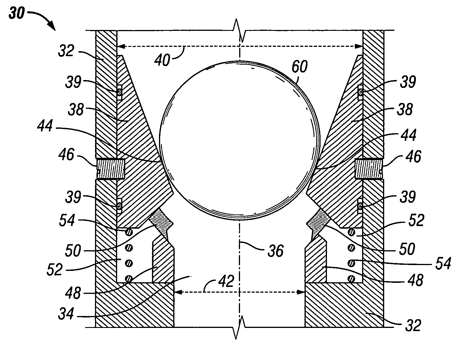
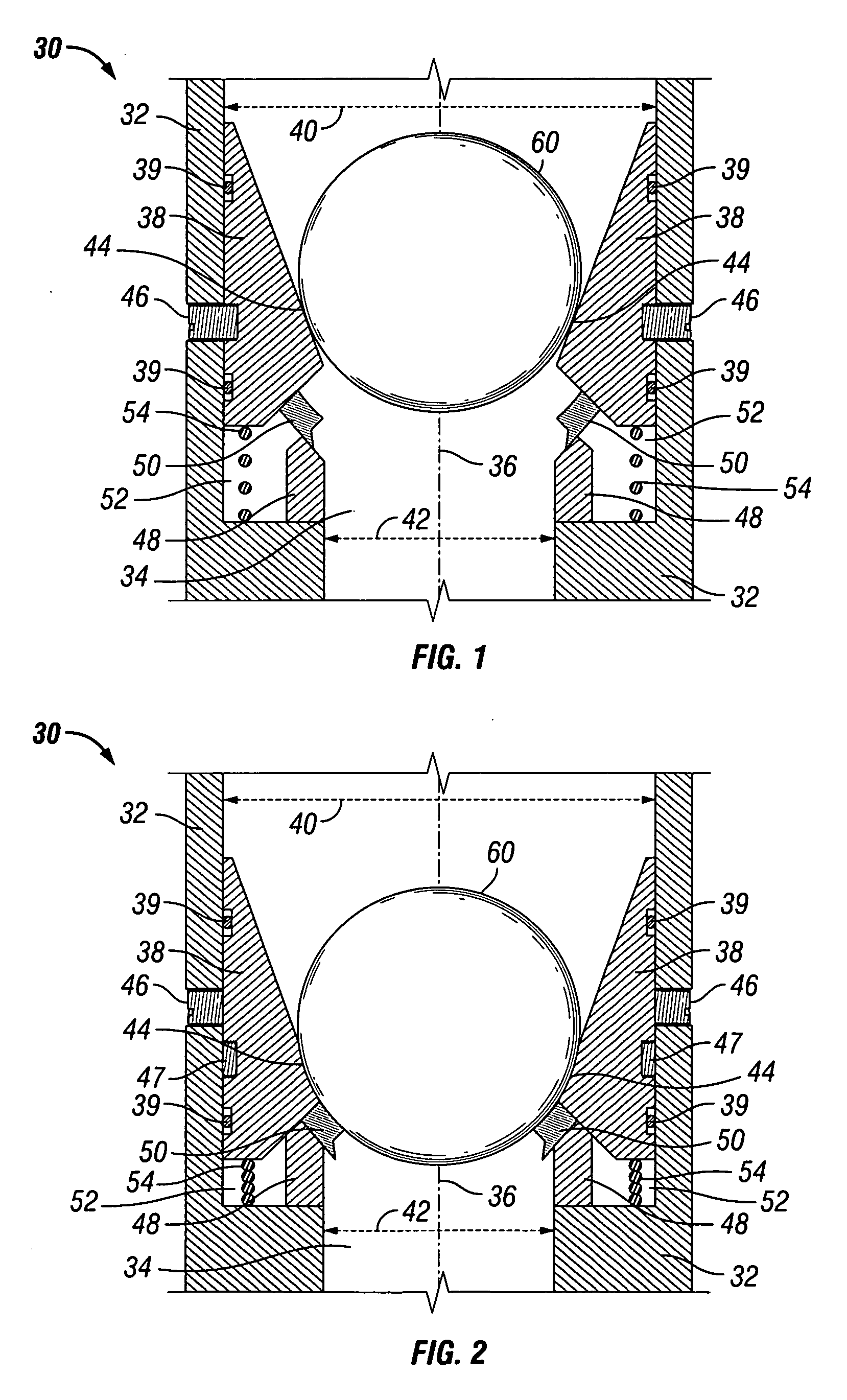
[0026]Referring now to FIGS. 1-2, in one embodiment, ball seat 30 includes a sub or housing 32 having bore 34 defined by an inner wall surface and having axis 36. Bore 34 includes seat 38 for receiving plug element 60, shown as a ball in FIGS. 1-2. Seat 38 includes a housing engagement surface in sliding engagement with the inner wall surface of housing 32 (also referred to herein as a seat engagement surface) so that seat 38 has a first position (FIG. 1) and a second position (FIG. 2). In one embodiment, dynamic seals 39 assist in sliding engagement of seat 38 with the inner wall surface of housing 32. Seat 38 also includes contact area 44 for receiving plug element 60. Contact area 44 is shaped to form an engagement surface with plug element 60 that is reciprocal in shape to the shape of the plug element 60 (shown in FIGS. 1-2 as a ball). Thus, in this embodiment, plug element 60 is spherically-shaped and contact area 44 includes an arc shape. As mentioned above, however, although...


PUM


Abstract

Apparatuses for restricting fluid flow through a well conduit comprise a housing having a longitudinal bore and a seat disposed within the bore. The seat has a first position when the apparatus is in the run-in position and a second position when the apparatus is in the set position. The seat comprises an arcuate member comprising a plurality of slits defining a plurality of segment members having a gap there-between. Each of the gaps are variable such that movement of segment members inwardly causes the gaps to be narrowed or closed off completely when a plug element is disposed into the bore and landed on the arcuate member to move the arcuate member from the first position to the second position, causing restriction of fluid flow through the bore and the well conduit.

Description

RELATED APPLICATION[0001]This application is a continuation-in-part application of, and claims the benefit of, U.S. patent application Ser. No. 11 / 891,706, filed Aug. 13, 2007.BACKGROUND[0002]1. Field of Invention[0003]The present invention is directed to ball seats for use in oil and gas wells and, in particular, to ball seats having a ball seat support member that provides support to the ball in addition to the support provided by the seat.[0004]2. Description of Art[0005]Ball seats are generally known in the art. For example, typical ball seats have a bore or passageway that is restricted by a seat. The ball or drop plug is disposed on the seat, preventing or restricting fluid from flowing through the bore of the ball seat and, thus, isolating the tubing or conduit section in which the ball seat is disposed. As the fluid pressure above the ball or drop plug builds up, the conduit can be pressurized for tubing testing or actuating a tool connected to the ball seat such as setting ...

Claims


Application Information

Patent Timeline
Patent Type & Authority Applications(United States)
IPC IPC(8): E21B34/06E21B34/08
CPCE21B34/14E21B33/1285
Inventor AVANT, MARCUS A.JOHNSON, CHARLES C.KING, JAMES G.RUDDOCK, DAVID B.SOLFRONK, MATTHEW D.KELLNER, JUSTIN
Owner BAKER HUGHES INC
Why Eureka
Try Eureka