Method for detecting formation pore pressure by detecting pumps-off gas downhole

a technology of pore pressure detection and pumping gas, which is applied in the direction of borehole/well accessories, survey, construction, etc., can solve the problems of insufficient weight of drilling fluid to maintain over-balance on the well, the wellbore portion of the formation can be detrimental, and the wellbore portion may be drilled slightly over-balanced

Inactive Publication Date: 2009-06-25
BP CORP NORTH AMERICA INC
View PDF44 Cites 44 Cited by
  • Summary
  • Abstract
  • Description
  • Claims
  • Application Information

AI Technical Summary

Benefits of technology

[0031]Detection of pumps-off gas downhole and communication of that information (or information indicative of the presence of pumps-off gasses) to a human-readable interface at the surface would allow the assessment of formation pressure relative to wellbore pressure in a much quicker and timelier manner, which should result in a more accurate assessment of formation pore pressure and reduced associated drilling problems such as fluid influxes, lost circulation or wellbore instability. In certain embodiments, the method further comprises using the information on whether pressure of the wellbore fluid is greater than the formation fluid pressure to locate a point of lost circulation or a well fluid influx in the well. In yet other methods, the information on location of lost circulation or well fluid influx may be used to diagnose the root cause of the lost circulation or fluid influx. In still other methods, once the root cause of the lost circulation or well fluid influx is diagnosed, the method comprises selecting an appropriate treatment, and placing a well treatment where the problem has developed in the well.

Problems solved by technology

Drilling fluid components in the well formation faces and near-wellbore portions of the formation can be detrimental to the production of fluids from the formation after the well has been completed.
In other instances, the well may be drilled slightly over-balanced but the drilling fluid may have a weight insufficient to maintain over-balance on the well if the pumps are stopped.
This is also an under-balanced condition when the pumps are off.
When an over-balanced condition exits, portions of the drilling fluid will enter the permeable formations and constitute an obstacle to the production of fluids from those formations.
When the high pressure high permeability reservoirs are exposed to the lower pressure mud columns in pumps-on or pumps-off state, the fluids in the formation can flow into the well at high rates and volume and produce the kick that creates the unstable and potentially unsafe condition drilling operators desire to avoid.
This is an effective method for determining how much gas may be in the drilling fluid but unfortunately in a well of any substantial depth it may take two to three hours for this drilling fluid to reach the earth surface.
This may be too late to avoid drilling into a high-pressure permeable formation without making adequate preparations.
Failure to take adequate preparations before drilling into a permeable high-pressure formation may result in a kick and potential blowout.
This difference in pressure results in a change in the differential pressure between the formation and the borehole.
This can take many hours to do and usually results in a significant delay in understanding if the phenomena is occurring and assessing the magnitude of the formation pressure relative to the drilling fluid pressure.
Applicant's previously filed application Ser. No. 12 / 004,175 describes how to analyze gas content in drilling fluids in the annulus; however, the most suitable gas detection devices used downhole to monitor gases in the annulus are not capable of distinguishing freshly introduced formation gas from circulated gas.

Method used


Image

  • Method for detecting formation pore pressure by detecting pumps-off gas downhole
  • Method for detecting formation pore pressure by detecting pumps-off gas downhole
  • Method for detecting formation pore pressure by detecting pumps-off gas downhole

Examples


Embodiment Construction

[0049]In the following description, numerous details are set forth to provide an understanding of the disclosed methods and apparatus. However, it will be understood by those skilled in the art that the methods and apparatus may be practiced without these details and that numerous variations or modifications from the described embodiments may be possible.

[0050]In the discussion of the drawing figures, the same numbers will be used throughout to refer to the same or similar components.

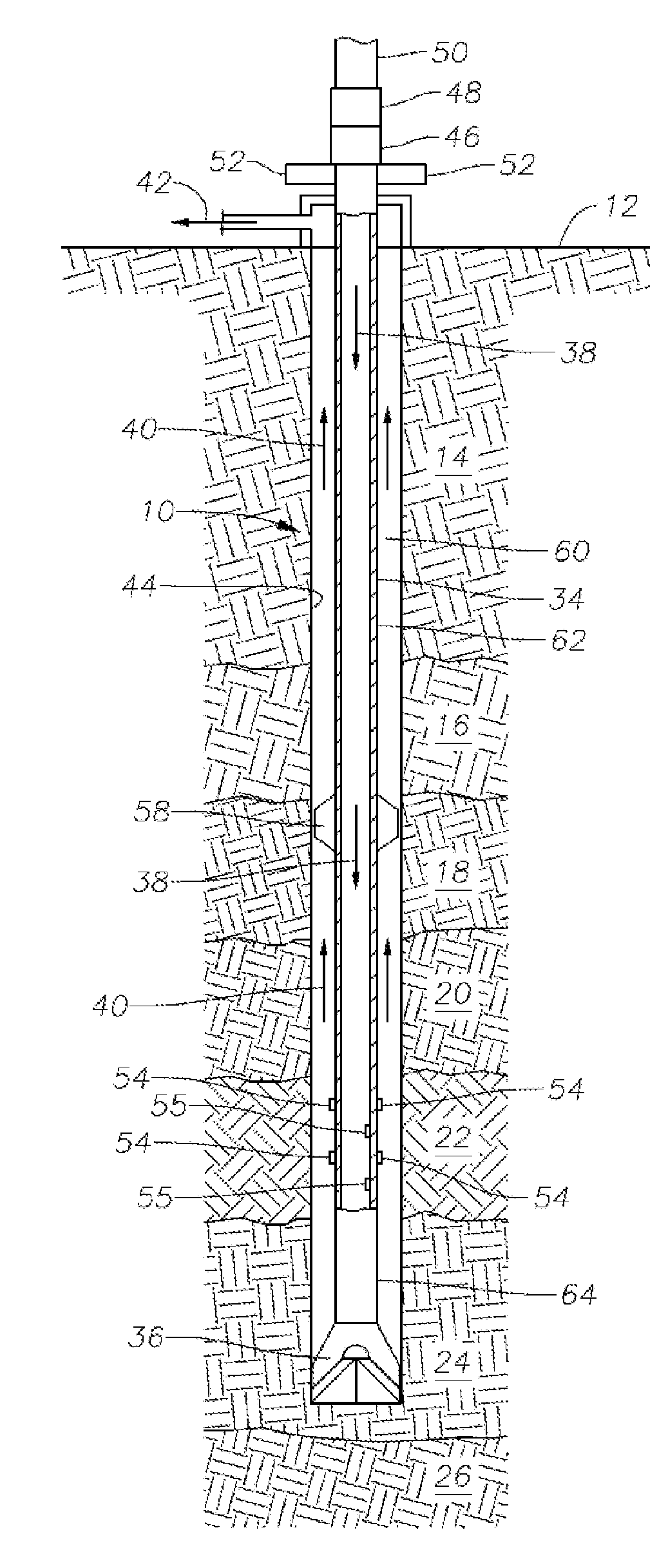
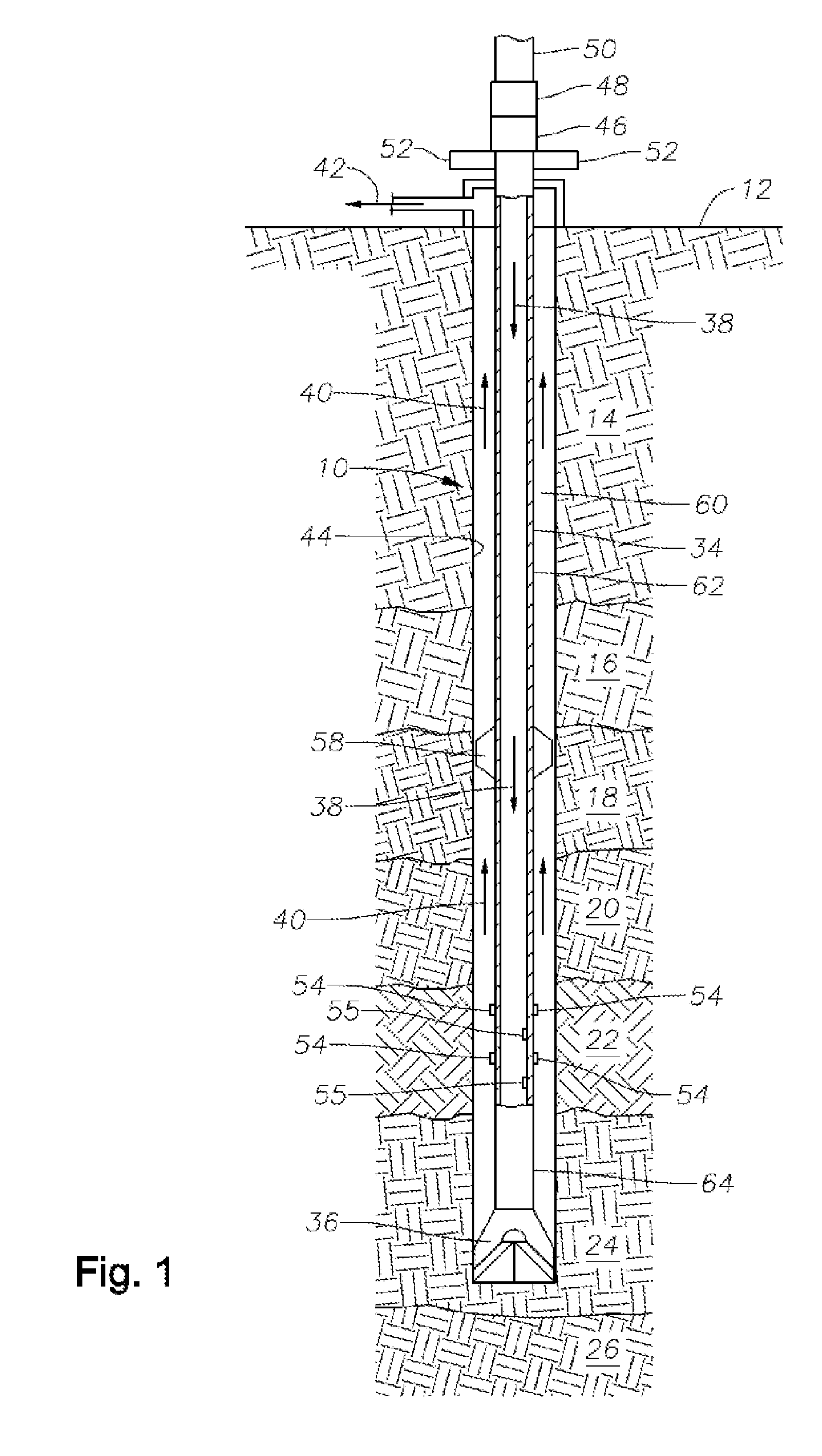
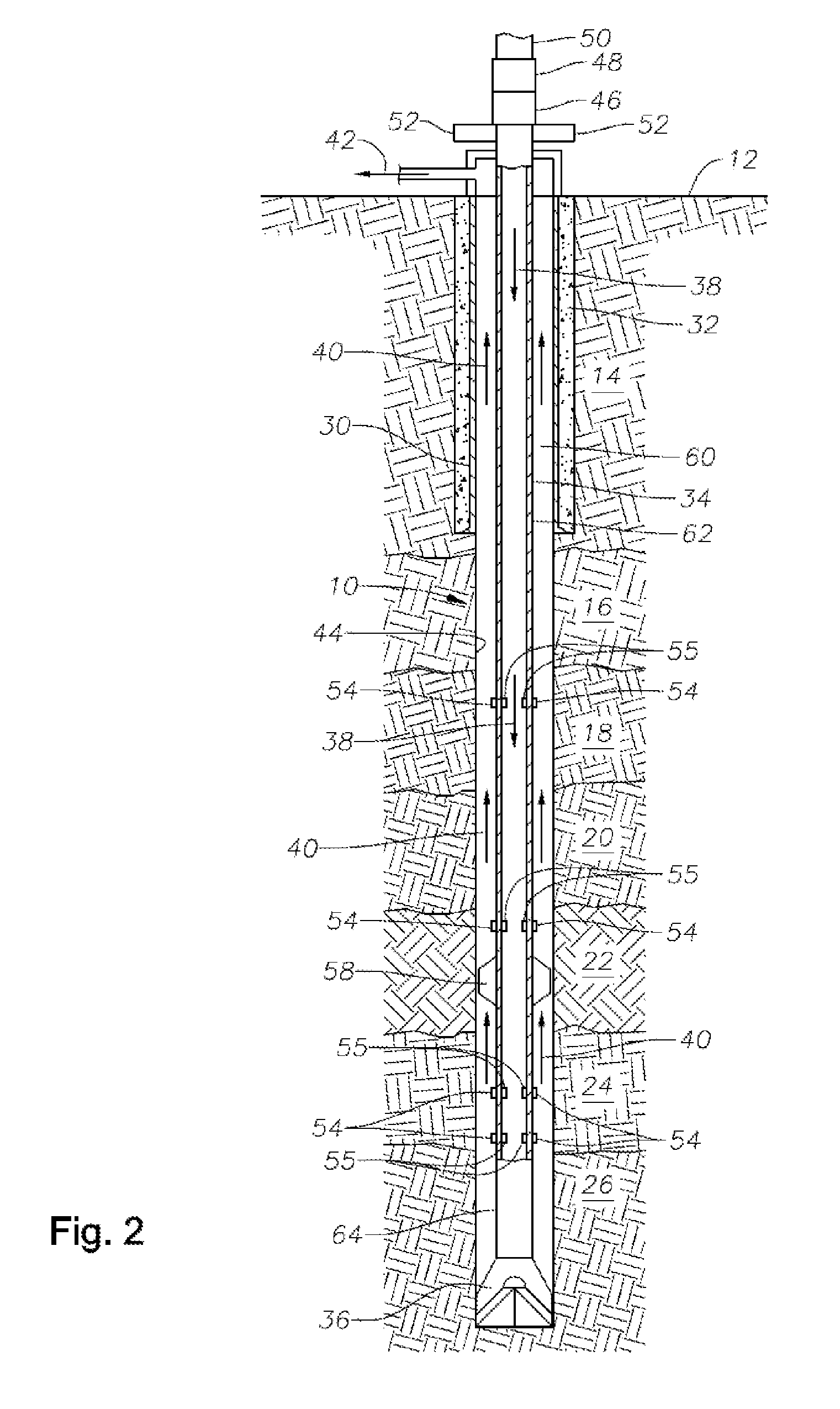
[0051]As illustrated in FIG. 1, a wellbore 10 extends from an earth surface 12 through an overburden 14 and through formations 16, 18, 20, 22, 24 and 26. Some of these formations may be oil-bearing or gas-bearing formations while others may be shale formations which contain pressured fluids. A drill pipe (also referred to herein as a drill string) 34 is positioned to extend from the earth surface to a drill bit 36. Drilling fluid is pumped through the drill string as illustrated by arrows 38 and recover...


PUM


Abstract

Methods and systems are described for drilling a well while distinguishing circulated gas or air from pumps-off gas in a drilling fluid at downhole pressure and temperature. A well is drilled with a drilling fluid, drill string, and drill bit. Drilling fluid is pumped through the drill string, drill bit, and into an annulus between the drill string and a wellbore. The drill string comprises one or more sensors sensing a parameter indicative of circulated gas or air in the drilling fluid flowing through the drill string, one or more sensors being behind and near the drill bit. The sensors measuring gas in the drill string may be at the same level as gas detectors in the annulus. The measurements are communicated to a human-readable interface at the surface, allowing an operator to determine if pressure of the wellbore fluid is greater than formation fluid pressure.

Description

CROSS-REFERENCE TO RELATED APPLICATIONS[0001]The present application is a continuation-in-part of, and claims benefit under 35 U.S.C. § 120 from application Ser. No. 12 / 004,175, filed Dec. 19, 2007, which is incorporated herein by reference in its entirety.STATEMENT REGARDING FEDERALLY SPONSORED RESEARCH OR DEVELOPMENT[0002]Not applicable.BACKGROUND OF THE INVENTION[0003]The present disclosure relates in general to methods of drilling wellbores, for example, but not limited to, wellbores for producing hydrocarbons from subterranean formations, and more particularly to methods of distinguishing circulated gases from connection gas or gas influx in a drilling oil or gas well.BACKGROUND ART[0004]Drilling techniques for producing wellbores to great depths in the earth are well known and are widely used, especially in the exploration for and production of hydrocarbons. These wells are typically produced by the use of a drill bit positioned on the lower end of a drill string which is supp...

Claims


Application Information

Patent Timeline
Patent Type & Authority Applications(United States)
IPC IPC(8): E21B49/00
CPCE21B21/00E21B44/00E21B21/08E21B21/085
Inventor ALBERTY, MARK W.
Owner BP CORP NORTH AMERICA INC
Why Eureka
Try Eureka