Digital Photo Frame with Power Saving Function and Related Power Saving Method
Active Publication Date: 2009-06-25
WISTRON CORP
View PDF12 Cites 60 Cited by
Summary
Abstract
Description
Claims
Application Information
AI Technical Summary
This helps you quickly interpret patents by identifying the three key elements:
Problems solved by technology
Method used
Benefits of technology
Benefits of technology
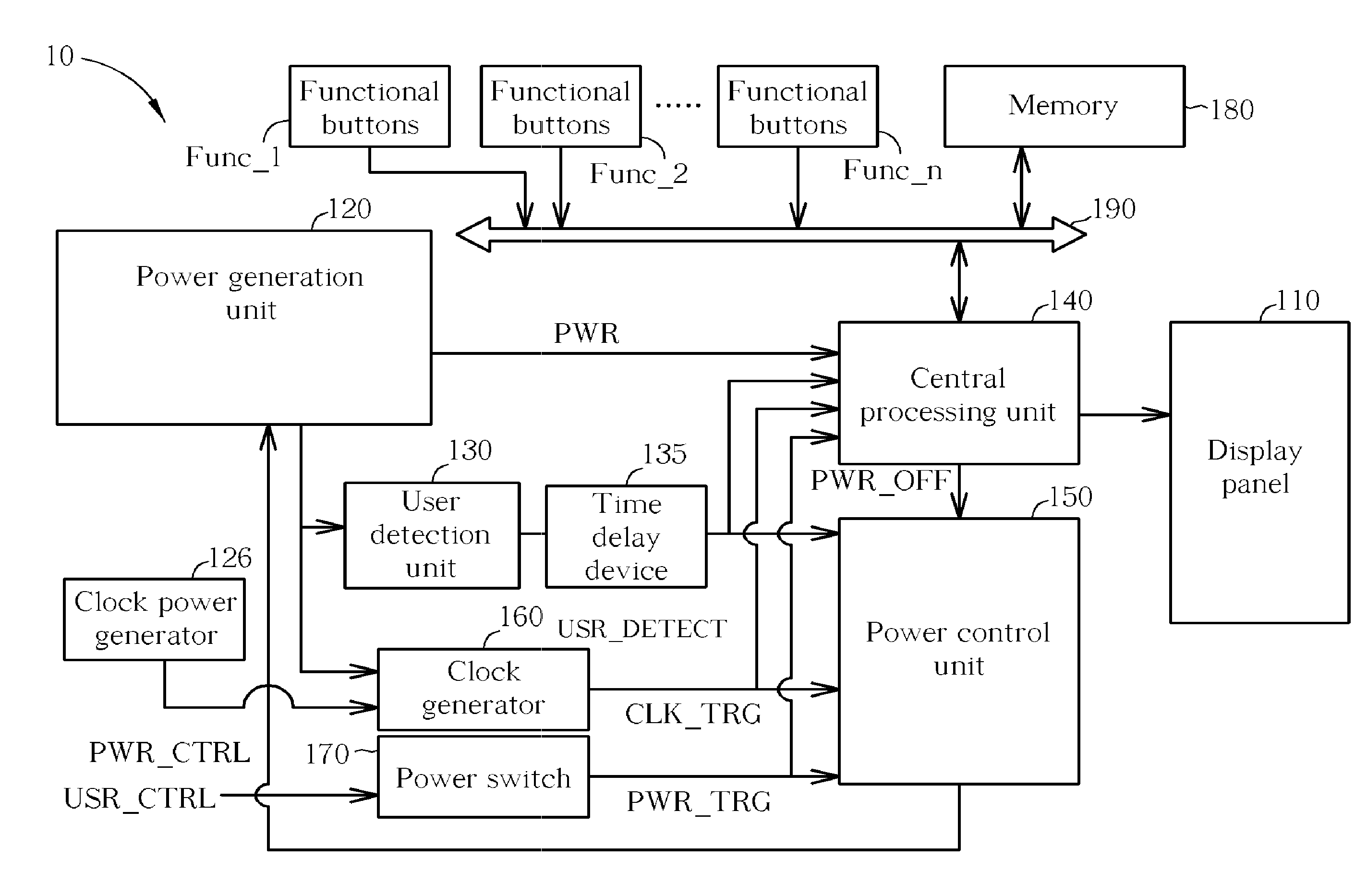
[0008]The present invention discloses a digital photo frame with power saving functions, which comprises a display panel, a power generation unit, a user detection unit, a central processing unit and a power control unit. The power generation unit is utilized for providing a system power and switching the system power according to a power control signal. The user detection unit, installed in the display panel, is utilized for detecting presence of a user within a specific range to generate a user detection signal. The central processing unit, coupled to the power generation unit and the user detection unit, is utilized for
Problems solved by technology
For an electronic device equipped with a display panel, such as a digital photo frame, a great amount of system power is consumed in operating the display panel.
In portable products, which use batteries as a power source, standby time is greatly limited.
Thus, power-saving design becomes a very important issue.
In other words, the display panel consumes about one-third of the total system power.
However, in each of these two methods, the electronic device cannot accurately detect the presence of users when performing the power saving operations.
For example, a digital photo frame may continue displaying pictures on its display panel when the user leaves, which causes unnecessary waste of system power.
Method used
Image
Click on the blue label to locate the original text in one second.
Reading with bidirectional positioning of images and text.
Examples
first embodiment
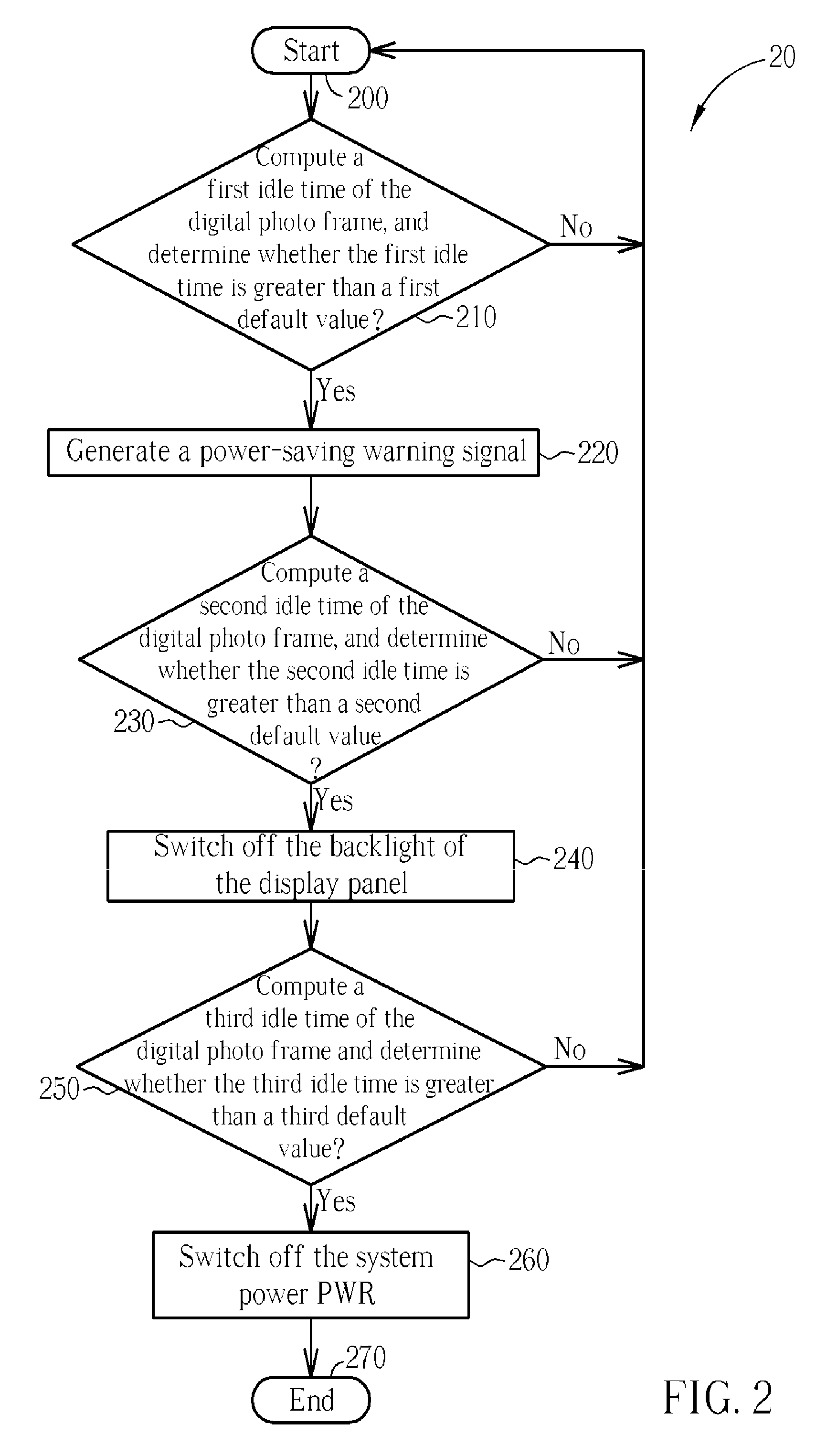
[0020]Please refer to FIG. 2. FIG. 2 is a schematic diagram of a power saving process 20 according to the present invention. The power saving process 20 is utilized for realizing the power saving functions of the digital photo frame 10, and includes the following steps:
[0021]Step 200: Start.
[0022]Step 210: Compute a first idle time of the digital photo frame 10, and determine whether the first idle time is greater than a first default value. If so, proceed to Step 220; and if not, proceed to Step 200.
[0023]Step 220: Generate a power-saving warning signal.
[0024]Step 230: Compute a second idle time of the digital photo frame 10, and determine whether the second idle time is greater than a second default value. If so, proceed to Step 240; and if not, proceed to Step 200.
[0025]Step 240: Switch off the backlight of the display panel 110.
[0026]Step 250: Compute a third idle time of the digital photo frame 10 and determine whether the third idle time is greater than a third default value. ...
second embodiment
[0035]Please continue to refer to FIG. 3. FIG. 3 is a schematic diagram of a power saving process 30 according to the present invention. The power saving process 30 is utilized for realizing the power saving functions of the digital photo frame 10, and includes the following steps:
[0036]Step 300: Start.
[0037]Step 310: Compute a first idle time of the digital photo frame 10, and determine whether the first idle time is greater than a first default value. If so, proceed to Step 320; and if not, proceed to Step 300.
[0038]Step 320: Dim the backlight intensity of the display panel 110.
[0039]Step 330: Compute a second idle time of the digital photo frame 10, and determine whether the second idle time is greater than a second default value. If so, proceed to Step 340; and if not, proceed to Step 300.
[0040]Step 340: Determine whether the backlight intensity of the display panel 110 is dimmed to be off. If so, proceed to Step 350; and if not, proceed to Step 320.
[0041]Step 350: Compute a thi...
PUM
Abstract
A digital photo frame having power saving functions includes a display panel, a power generation unit for switching a system power according to a power controlsignal, a user detection unit installed on the display panel for detecting whether a user exists within a specific range to generate a user detection signal, a central processing unit for adjusting backlight intensity of the display panel when the system power is provided by the power generation unit according to the user detection signal and for generating a power switch-off signal when the backlight intensity of the display panel is turned off according to the user detection signal, and a power control unit for generating the power control signal to switch off the system power when the backlight intensity of the display panel is adjusted to be switched off according to the power switch-off signal.
Description
BACKGROUND OF THE INVENTION[0001]1. Field of the Invention[0002]The present invention relates to a digital photo frame with a power saving function, and more particularly, to a digital photo frame that senses presence of a user within a specific range as a basis of power saving operations.[0003]2. Description of the Prior Art[0004]For an electronic device equipped with a display panel, such as a digital photo frame, a great amount of system power is consumed in operating the display panel. In portable products, which use batteries as a power source, standby time is greatly limited. Thus, power-saving design becomes a very important issue.[0005]Taking a 3.5-inch digital photo frame as an example, typical power consumption of the display panel is roughly between 0.384 and 0.41 Watts, whereas power consumption of the rest of the digital photo frame amounts to only 0.85 Watts. In other words, the display panel consumes about one-third of the total system power. Thus, if power saving mea...
Claims
Application Information
Patent Timeline
Application Date:The date an application was filed.
Publication Date:The date a patent or application was officially published.
First Publication Date:The earliest publication date of a patent with the same application number.
Issue Date:Publication date of the patent grant document.
PCT Entry Date:The Entry date of PCT National Phase.
Estimated Expiry Date:The statutory expiry date of a patent right according to the Patent Law, and it is the longest term of protection that the patent right can achieve without the termination of the patent right due to other reasons(Term extension factor has been taken into account ).
Invalid Date:Actual expiry date is based on effective date or publication date of legal transaction data of invalid patent.

