Structure for drawing out lead wires from a coil device

Inactive Publication Date: 2009-06-25
FUJIKOKI CORP
View PDF4 Cites 5 Cited by
  • Summary
  • Abstract
  • Description
  • Claims
  • Application Information

AI Technical Summary

Benefits of technology

[0010]According to the structure of the present invention, since ends of lead wires are connected to a connector, and the lead wires are connected to a wiring board for relay via the connector, exposed conductor portions of the lead wires are not subject to preliminary soldering. As a result, when a mechanical load is applied to the lead wires from outside, the breakage of the exposed conductor portion can be prevented, and the connection state between the lead wires and the coil is maintained in stable.
[0012]In the above-mentioned structure for drawing out lead wires from the coil device, the coil device may be a resin-molded type in which an outer periphery of the coil is resin-molded except for tip portions of the terminal pins, and a cover for covering the connector to which the lead wires are connected, the wiring board and the terminal pins can be connected to the resin-molded coil device, and an inner space of the cover may be filled with resin. By this structure, the wiring board is stably retained in the cover, which allows the lead wires also to be stably retained in the cover.
[0013]Further, the present invention relates to a structure for drawing out lead wires of a coil device for drawing lead wires from terminal pins of a coil device having a coil and a plurality of terminal pins to which ends of the coil are connected, and the structure is characterized in that to ends of the lead wires are connected crimp terminals; the crimp terminals are connected at a side face thereof to a wiring board for relay; and the wiring board is connected to the terminal pins. According to the present invention, since ends of lead wires are connected to crimp terminals, and the lead wires are connected to a wiring board for relay via the crimp terminals, exposed conductor portions of the lead wires are not subject to preliminary soldering. As a result, when mechanical load is added to the lead wires from outside, the breakage of the exposed conductor portions can be prevented, and the connection state between the lead wires and the coil is stably maintained.
[0015]In the structure for drawing out lead wires from the coil device described above, the coil device can be a resin-molded coil device in which an outer periphery of the coil is resin-molded except for tip portions of the terminal pins, and a cover for covering the crimp terminals to which the lead wires are connected, the wiring board and the terminal pins may be connected to the resin-molded coil device, and an inner space of the cover can be filled with resin. By this structure, the wiring board is stably retained in the cover, which allows the lead wires also to be stably retained in the cover.
[0016]As described above, according to the present invention, when a load is added to lead wires under the condition that the lead wires of a coil device are connected to and retained on a wiring board, it becomes possible to prevent exposed conductor portions of the lead wires from breaking and to maintain the connection state between the lead wires and the wiring board.

Problems solved by technology

Therefore, after the exposed conductor portion 68a is soldered to the conductive pattern of the wiring board 67, a load to the lead 68 may break the portion of the exposed conductor portion 68a subject to preliminary soldering, and there is a problem that uneasiness remains in respect of strength.

Method used


Image

  • Structure for drawing out lead wires from a coil device
  • Structure for drawing out lead wires from a coil device
  • Structure for drawing out lead wires from a coil device

Examples


Embodiment Construction

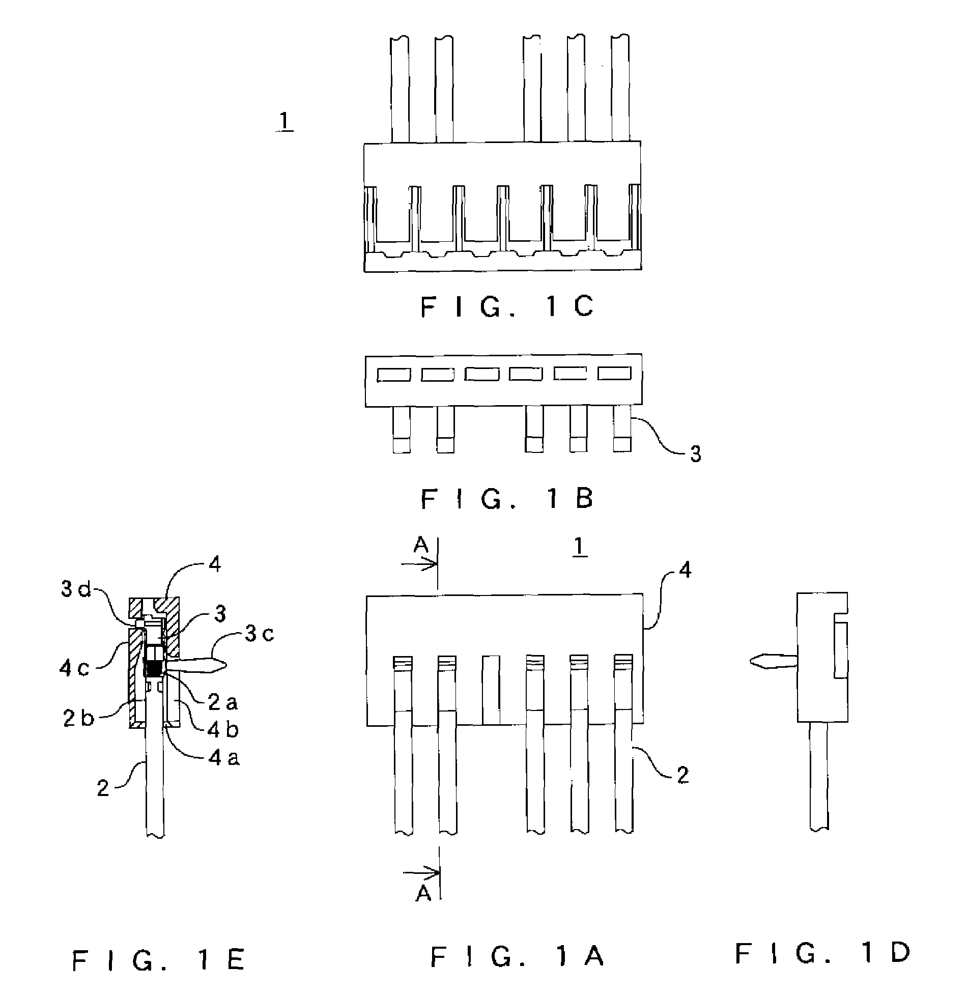
[0027]Embodiments of the present invention will be explained hereunder with reference to drawings. In the below explanation also, in the same manner as the above description of the related art, the present invention is adapted to the coil device 65 of a stepping motor for driving an electromagnetic valve show in FIG. 9.

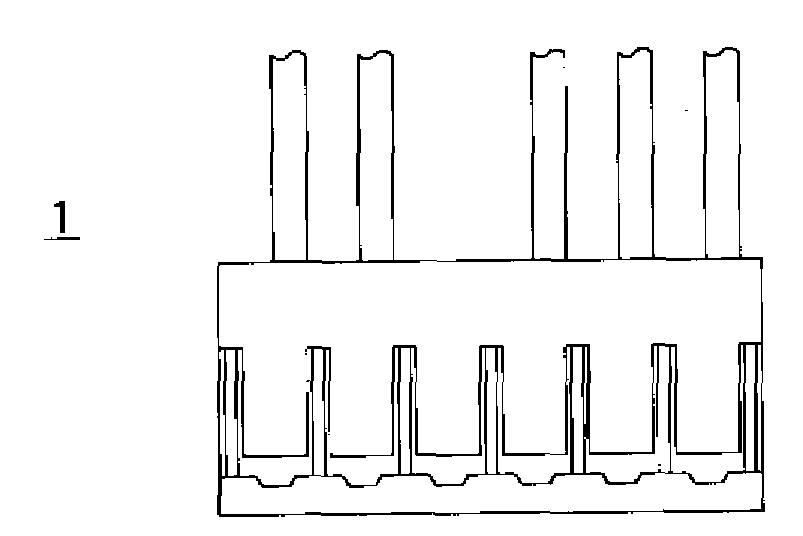
[0028]FIGS. 1A to 1E show a connector constituting a structure for drawing out lead wires from a coil device according to the present invention, and the connector 1 is composed of lead wires 2, crimp terminals 3 attached to tip portions of the lead wires 2, and a housing 4 for retaining the lead wires 2 by the engagement with the crimp terminals 3.

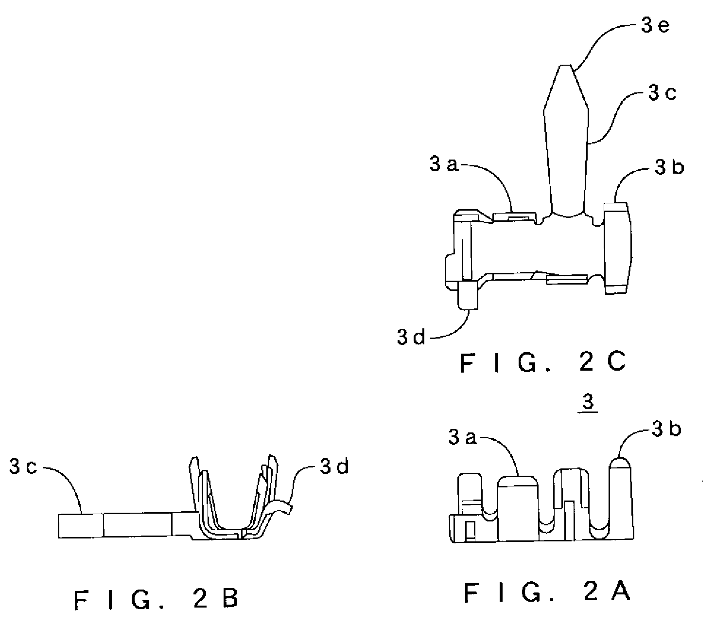
[0029]The crimp terminal 3 is made of thin metal, and as shown in FIGS. 2A to 2C, the crimp terminal 3 is provided with an exposed conductor portion gripping portion 3a for gripping an exposed conductor portion 2a of the lead wire 2 (shown in FIGS. 1A to 1E), a gripping portion 3b for gripping a covered portion 2b of the lea...


PUM


Abstract

To prevent an exposed conductor portion from breaking and to maintain connection state between lead wires and a wiring board even when a load is added to the lead wires under the condition that the lead wires for a coil device is connected to and retained on the wiring board. In a structure for drawing out lead wires from a coil device according to the present invention, for drawing a lead wire from a terminal pin of a coil device 65 having a coil 62 and a plurality of terminal pins to which ends of the coil are connected, an end of the lead wire 2 is connected to a connector 1, the connector is connected at a side face thereof to a wiring board 67 for relay, and the wiring board is connected to the terminal pin. A connection terminal of the connector is connected to the wiring board in a direction perpendicular to a direction that the lead wire extends. In another case, after an end of the lead wire is connected a crimp terminal 3, the crimp terminal is connected at a side face thereof to a wiring board for relay, and thereafter the wiring board is connected to the terminal pin.

Description

CROSS-REFERENCE TO RELATED APPLICATIONS[0001]The present application claims priority to Japanese Patent Application No. 2007-331348 entitled STRUCTURE FOR DRAWING OUT LEAD WIRES FROM A COIL DEVICE filed on Dec. 25, 2007.STATEMENT RE: FEDERALLY SPONSORED RESEARCH / DEVELOPMENT[0002]Not ApplicableBACKGROUND[0003]1. Field of the Invention[0004]The present invention relates to a structure for drawing out lead wires from a coil device, which is used for energizing a coil winding wound around a coil bobbin, such as an electromagnetic coil device or the like.[0005]2. Description of the Related Art[0006]A conventional electromagnetic valve described in Japanese patent publication No. 2005-291266 gazette, as shown in FIG. 9, a coil device 65 of a stepping motor 60 for driving the electromagnetic valve is composed of: a coil bobbin 61; a coil 62 wound around the coil bobbin 61; a terminal pin 63 to which an end of the coil 62 is connected; and a resin mold portion 64 resin-molding the coil bobb...

Claims


Application Information

Patent Timeline
IPC IPC(8): H01F27/29
CPCH01F5/04H01F7/06H01F27/04H01R4/023H04R2209/041H01R13/6658H01R2201/22H04R9/046H01R13/567F16K31/04H01R12/75
Inventor KOYATSU, KAORU
Owner FUJIKOKI CORP
Why Eureka
Try Eureka