Refractive-index measurement system and method for measuring refractive-index

a measurement system and refractive index technology, applied in the field of refractive index measurement system and method, can solve the problems of inability to precisely detect the magnitude of the change in refractive index, internal force can be generated within the body of the lens,

Inactive Publication Date: 2009-06-25
HON HAI PRECISION IND CO LTD
View PDF2 Cites 17 Cited by
  • Summary
  • Abstract
  • Description
  • Claims
  • Application Information

AI Technical Summary

Benefits of technology

[0002]The present invention generally relates to a measurement system and method, and particularly to a measurement system and method for measuring a change in the refractive index of a lens.

Problems solved by technology

However, internal force can be generated within a body of the lens due to defects on the molds or imprecision in manufacturing, with internal stress distributed where the internal force occurs.
However, such measures cannot precisely detect the magnitude of the change in the refractive index.

Method used


Image

  • Refractive-index measurement system and method for measuring refractive-index
  • Refractive-index measurement system and method for measuring refractive-index
  • Refractive-index measurement system and method for measuring refractive-index

Examples


Embodiment Construction

[0016]Reference will now be made to the drawings to describe embodiments of the present refractive-index measurement system and method in detail.

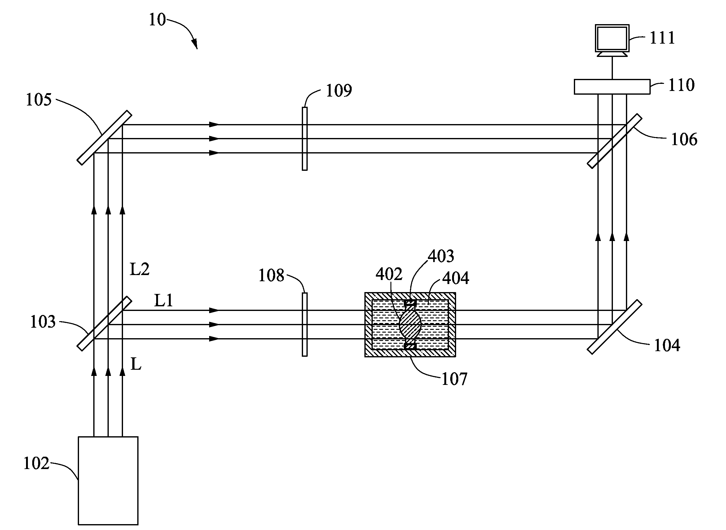
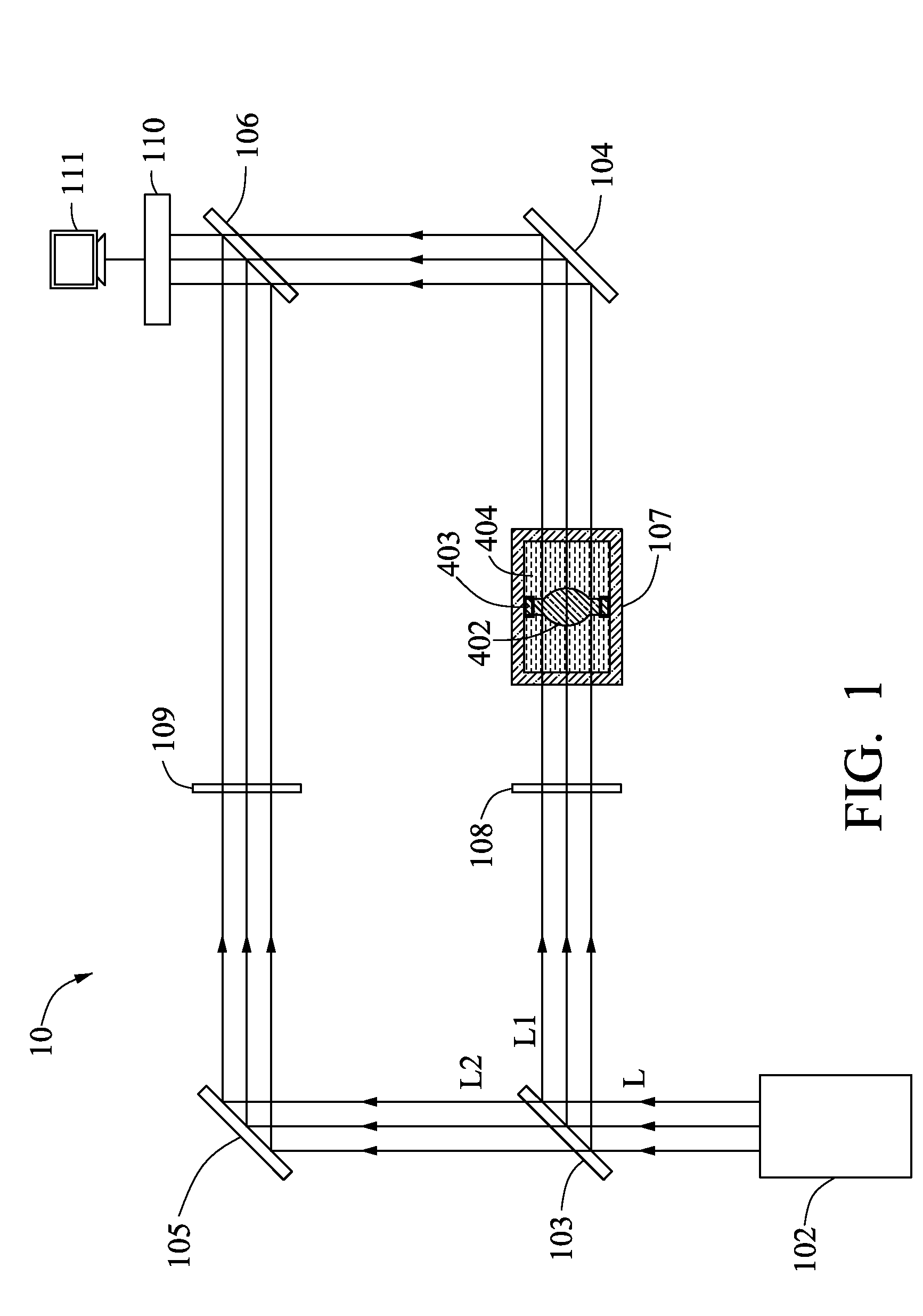
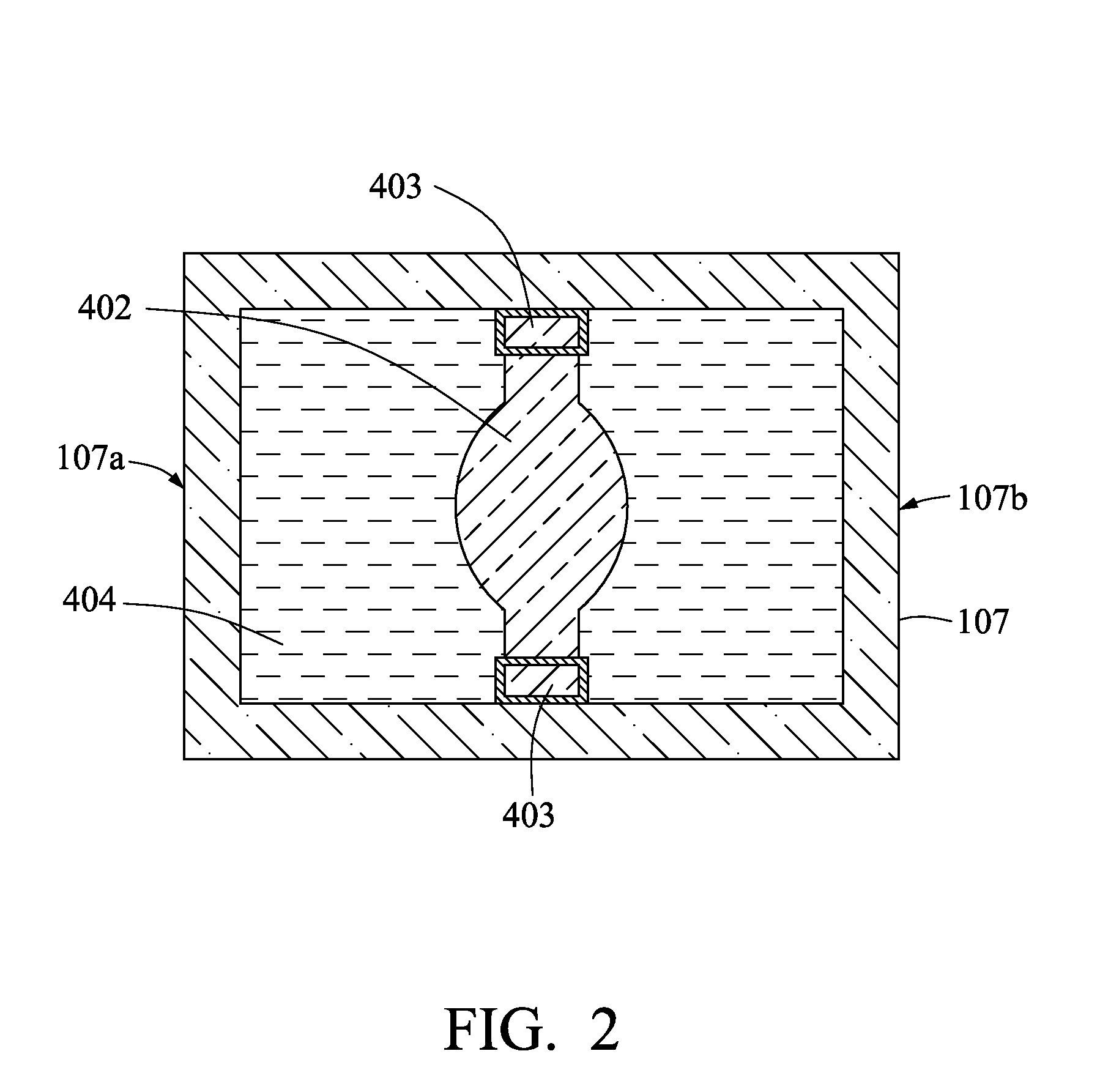
[0017]Referring to FIG. 1, a refractive-index measurement system 10 in accordance with an exemplary embodiment, is shown. The refractive-index measurement system 10 is configured for measuring a change in the refractive index of a lens 402. In such case, the lens 402 has a theoretical refractive index na, which represents a refractive index of the lens with no internal stress present. Changes in the refractive index relative to the theoretical refractive index na occur when internal force is generated within the lens 402. The refractive-index measurement system includes a light source 102, a first beam splitter 103, a first reflective mirror 104, a second reflective mirror 105, a second beam splitter 106, a container 107, a first polarizer 108, and a second polarizer 109.

[0018]The light source 102 emits light L to the first beam splitter 10...


PUM

PropertyMeasurementUnit
thickness daaaaaaaaaaa
daaaaaaaaaaa
refractive indexaaaaaaaaaa

Abstract

A refractive-index measurement system includes a light source, a first beam splitter, a first reflective mirror, a second reflective mirror, a second beam splitter, a container, a first polarizer, and a second polarizer. The first beam splitter splits light emitted from the light source into first and second light beams. The first light beam and the second light beam are reflected by the first reflective mirror and the second reflective mirror, respectively, incident into the second light beam splitter. The container is positioned along an optical pathway of first light beam. The container accommodates a lens and is filled with a medium having a refractive index substantially the same as a theoretical refractive index of the lens. The first polarizer is positioned along the optical pathway of the first light beam. The second polarizer is positioned along an optical pathway of the second light beam.

Description

BACKGROUND[0001]1. Field[0002]The present invention generally relates to a measurement system and method, and particularly to a measurement system and method for measuring a change in the refractive index of a lens.[0003]2. Description of Related Art[0004]Generally, optical lenses are manufactured by injection molding, which is advantageous for mass production at a low cost. During injection molding of the lenses, upper and lower molds are assembled to correspond to the desired contour of the lens, which is formed by injecting a molten material into a space between the molds.[0005]However, internal force can be generated within a body of the lens due to defects on the molds or imprecision in manufacturing, with internal stress distributed where the internal force occurs. A change in the refractive index of the lens may correspondingly occur in the area where the internal stress is distributed.[0006]Referring to FIG. 4, a conventional measurement system 20 for detecting a change in t...

Claims


Application Information

Patent Timeline
Patent Type & Authority Applications(United States)
IPC IPC(8): G01N21/41
CPCG01M11/0228
Inventor YUAN, KUN-I
Owner HON HAI PRECISION IND CO LTD
Why Eureka
Try Eureka