Ink jet recording apparatus and ink jet printing method

a recording apparatus and ink jet printing technology, applied in the direction of digitally marking record carriers, visual presentation using printers, instruments, etc., can solve the problems of image quality deterioration, uneven density of printed images, image deterioration

Inactive Publication Date: 2009-06-25
CANON KK
View PDF8 Cites 13 Cited by
  • Summary
  • Abstract
  • Description
  • Claims
  • Application Information

AI Technical Summary

Benefits of technology

[0019]The present invention has been made in consideration of the above-described circumstances, and an object thereof is to provide an ink jet printing apparatus and printing method in which image deterioration (unevenness) that may occur at the edges of printing areas can be reduced also for various printing media including unspecified printing media.
[0021]In accordance with the configuration above, image deterioration (unevenness) at the edges of a printing medium can be reduced for various printing media including unspecified printing media.

Problems solved by technology

In ink jet printing apparatuses, even a small amount of nozzle-by-nozzle structural variation that may occur during the process of manufacturing their print heads can affect the ejecting amount and direction of ink through each nozzle, which causes deterioration in image quality such as streaks and uneven density in printed images.
However, bi-directional multipath printing with a relatively small number of scanning (two to six times) may suffer from so-called “time difference unevenness” and therefore image deterioration.
In the case above, the image density (color tone) is accordingly different between the adjacent printing areas at the edges of the image, it may cause deterioration in image quality as uneven density at the predetermined width of printing area (a paper feed pitch).
Meanwhile, time difference unevenness is an image deterioration caused by a time difference between a previous scanning and printing and the next scanning and printing, and the degree of occurrence of unevenness depends significantly on the type of printing medium.
That is, the degree of ink penetration depends on the type of printing medium, which results in a significant difference in the degree of unevenness.
Therefore, in the printing apparatus that the most suitable printing ratio for reduction of time difference unevenness is arranged only for a specific type of printing medium, it may be impossible to reduce image deterioration due to time difference unevenness sufficiently when unspecified types of printing media are used.

Method used


Image

  • Ink jet recording apparatus and ink jet printing method
  • Ink jet recording apparatus and ink jet printing method
  • Ink jet recording apparatus and ink jet printing method

Examples


first embodiment

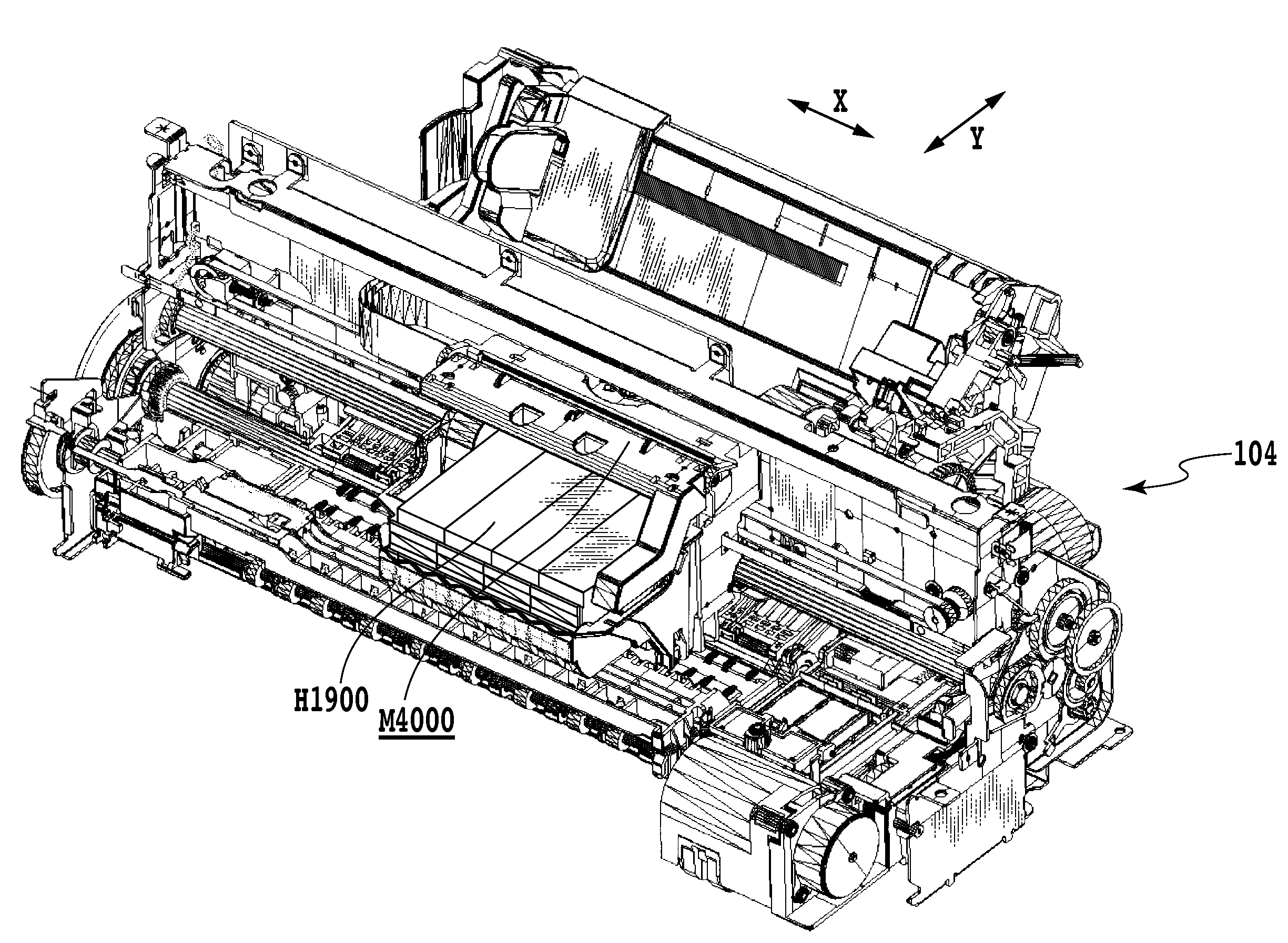
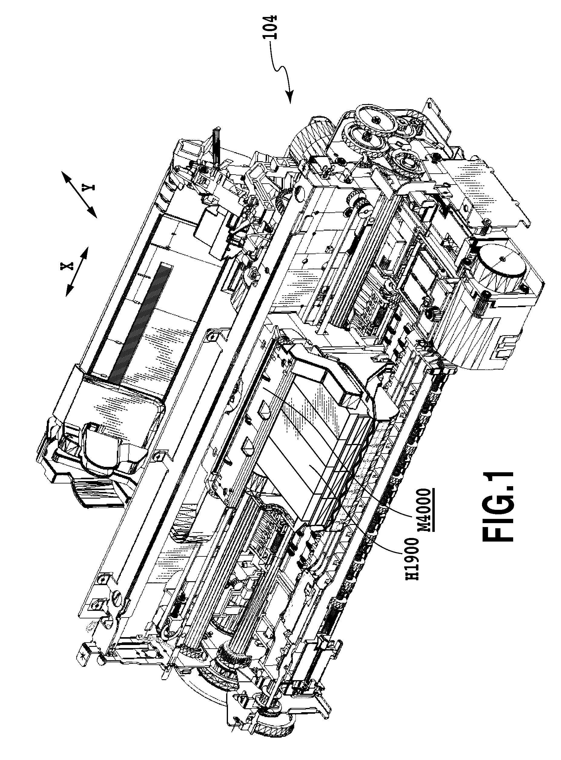
[0047]FIG. 1 is a perspective view showing an ink jet printing apparatus (printer) 104 according to the present embodiment. The carriage M4000 is equipped with print heads and ink tanks H1900 for supplying, respectively, C, M, Y, and K colors of ink to the print heads.

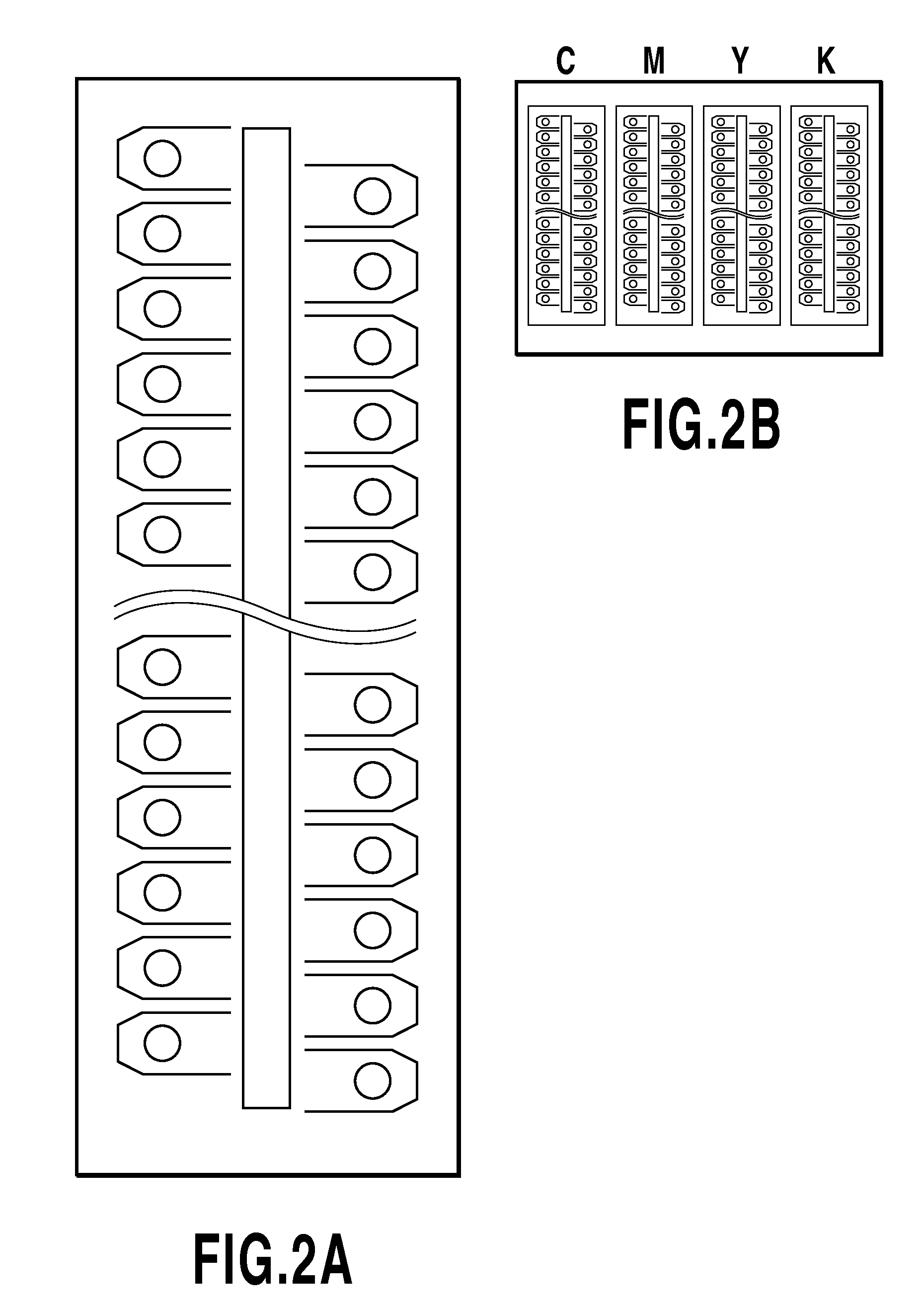
[0048]The printer 104 is a so-called serial type one in which a print head adapted to eject ink scans a printing medium during which the ink is ejected for printing. The print heads are prepared to correspond respectively to cyan (C), magenta (M), yellow (Y), and black (K) colors of ink. Then the print heads can scan a printing medium such as printing paper by being attached to the carriage.

[0049]The carriage M4000 moves in the main scan direction (X direction in the drawing) and each nozzle in the print heads ejects ink at a predetermined timing based on binary separate printing data. After one primary scanning of the print heads, the printing medium is conveyed in the sub-scan direction (Y direction in the drawing) b...

second embodiment

[0085]Although the first embodiment is for the case where a user selects the most suitable test pattern of smaller density difference from plurality test patterns differs of printing ratio based on visible of the user. However, the present invention is not restricted to such a case where a user makes a selection based on visible of the user. For example, a density sensor such as an optical sensor may be used to measure the optical characteristics of test patterns and thereby to select a test pattern of smaller density difference.

[0086]FIG. 13 is a flow chart schematically showing processing for printing ratio selection according to the present embodiment. Predetermined test patterns are first printed (S131), as is the case in the first embodiment. Next, a density sensor installed in the printer 104 is used to measure the optical characteristics (for example, reflective optical density) of the printed test patterns (S132). Then, a test pattern without unevenness is determined based o...

third embodiment

[0091]Although test patterns are printed in the entire width of main scan direction of a printing medium in the first and second embodiments, the present invention is not restricted to such test patterns. In the present embodiment, printing is not performed through the entire width of main scan direction of a printing medium, but is performed with a weight depending on the time difference between scanning thereof.

[0092]The present embodiment can be applied regardless of whether the size of a printing medium is given in advance. The case where the size of a printing medium is not given in advance will hereinafter be described. If the size of a printing medium is given in advance, test patterns may be printed based on a predefined time between scanning without calculating the time between scanning.

[0093]FIG. 15 is a flow chart schematically showing processing for printing ratio selection according to the present embodiment. The time difference between scanning is first calculated base...


PUM


Abstract

There is provided an ink jet printing apparatus in which unevenness that may occur at the edges of printing areas can be reduced also for various printing media including unspecified printing media. In the ink jet printing apparatus which uses a print head for ejecting ink and performs printing by scanning a predetermined area on a printing medium with the print head multiple times, the multiple times of scan including a forward scan and a backward scan, the apparatus comprising: a control unit that cases the print head to print patterns each of which is printed through multiple times of scan of the print head and has different portions in a time interval between the multiple times of scan, with different printing ratios for the multiple times of scan; and a setting unit that sets the printing ratios based on the test patterns.

Description

BACKGROUND OF THE INVENTION[0001]1. Field of the Invention[0002]The present invention relates to ink jet printing apparatuses and ink jet printing method, in which ink is ejected through nozzles provided in a print head to print an image.[0003]2. Description of the Related Art[0004]In ink jet printing apparatuses, even a small amount of nozzle-by-nozzle structural variation that may occur during the process of manufacturing their print heads can affect the ejecting amount and direction of ink through each nozzle, which causes deterioration in image quality such as streaks and uneven density in printed images. In order to eliminate such uneven image density, there has been proposed a multipath printing method (separate printing technique) in which a print head scans a predetermined area on a printing medium multiple times to print images sequentially. In the multipath printing method, the print head passes multiple times each printing area and the predetermined area are printed throu...

Claims


Application Information

Patent Timeline
Patent Type & Authority Applications(United States)
IPC IPC(8): G06F15/00
CPCB41J19/142B41J29/393B41J29/02G06F15/00
Inventor MABUCHI, HIDEHISASHIBATA, TSUYOSHI
Owner CANON KK
Why Eureka
Try Eureka