
Image processing apparatus, image forming apparatus, and image processing method

a technology of image processing and forming apparatus, applied in the field of image processing apparatus and image processing method, can solve the problems of color density unevenness and streaks in images, reducing color density change, and reducing printing speed

Inactive Publication Date: 2009-06-25
CANON KK
View PDF22 Cites 28 Cited by
  • Summary
  • Abstract
  • Description
  • Claims
  • Application Information

AI Technical Summary

Benefits of technology

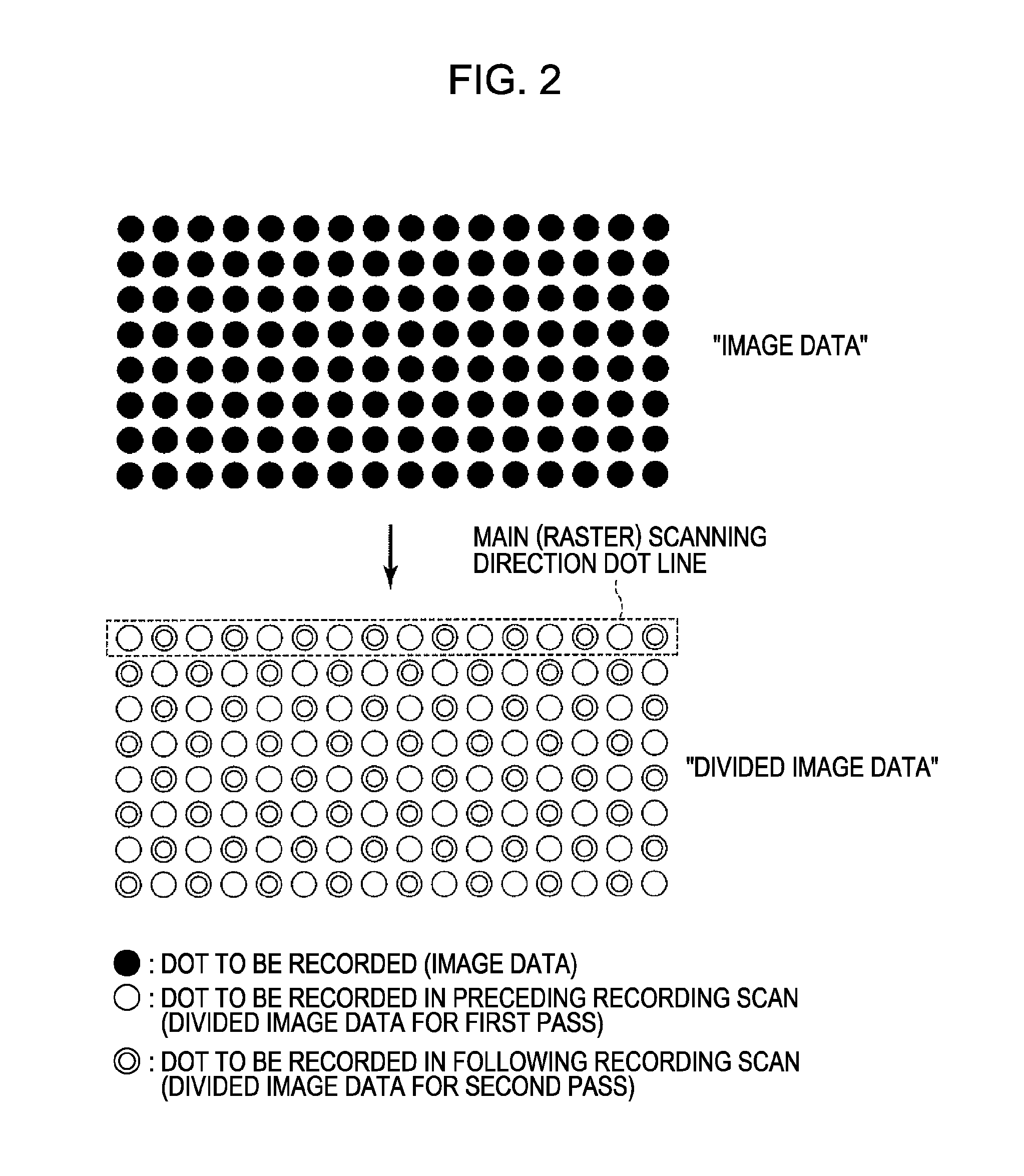
The present invention provides an image processing apparatus for processing, for each pixel, multivalued image data for a unit area of a recording medium, so as to form an image on the unit area with a plurality of relative movements between a recording head and the recording medium. The apparatus includes a selector capable of selecting between a first processing mode for dividing the multivalued image data into a plurality of pieces of multivalued image data corresponding to the plurality of relative movements, and quantizing each of the plurality of pieces of multivalued image data, or a second processing mode for quantizing the multivalued image data into quantized image data, and then dividing the quantized image data into a plurality of pieces of quantized image data corresponding to the plurality of relative movements. The apparatus can select between the first or second processing modes based on the content of the multivalued image data. This invention allows for more efficient processing of image data and improved image quality.

Problems solved by technology

Such variability may cause color density unevenness and streaks in images.
However, the printing speed may also reduce as the number of passes increases.
In such a circumstance, there is a need for reduction in a color density change and a color density unevenness that may result from a shift of the recording position (registration) of each printing scan or of each recording element line.
This change in the coverage ratio can cause a change in color density of the image.
Although the methods (hereinafter, referred to as a “multivalued data division method”) disclosed in Japanese Patent Laid-Open Nos. 2000-103088 and 2006-231736 provide robustness that may be superior to that provided by the mask-employing division method, the methods may also have disadvantages as compared to the mask-employing division method.
Since a division method may differ depending on a content(type) of image data in this manner, in certain instances it may not be as effective to employ the multivalued data division method, regardless of the content (type) of the image data.

Method used


Image

  • Image processing apparatus, image forming apparatus, and image processing method
  • Image processing apparatus, image forming apparatus, and image processing method
  • Image processing apparatus, image forming apparatus, and image processing method

Examples


exemplary embodiment 1

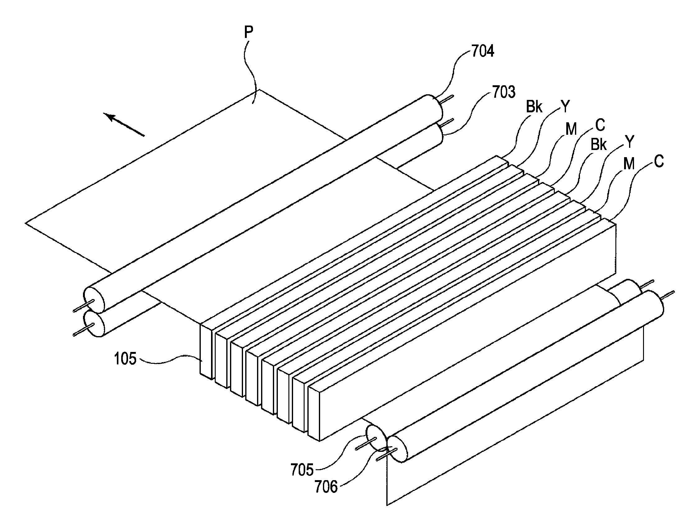
[0060]FIG. 1 is a schematic diagram for describing an internal configuration of a full-line type inkjet recording apparatus employed in the present invention. A recording medium P is fed by a feeding roller 705 and an auxiliary roller 706 and then conveyed in a direction of a conveying roller 704 and an auxiliary roller 703. The recording medium P is conveyed in a relative scanning direction (conveyance direction) indicated by an arrow while being sandwiched by these two pairs of rollers. During such an operation for conveying the recording medium P, ink is ejected from recording elements of recording heads 105 and an image is recorded on the recording medium P. This operation for conveying the recording medium corresponds to a relative scan (relative movement) between a recording medium and recording heads.

[0061]Two lines of the full-line type recording heads 105 may be arranged, for each of black (Bk), cyan (C), magenta (M), and yellow (Y) heads, in a parallel relationship to each...

exemplary embodiment 2

[0084]An exemplary embodiment 2 also employs a recording apparatus shown in FIG. 1 and an image processing process shown in FIG. 5, which have been described in the exemplary embodiment 1. However, a selecting unit 103 according to this exemplary embodiment does not select a mode in accordance with an attribute of image data as in the exemplary embodiment 1, but instead selects the mode in accordance with a grayscale level (0-255) of image data.

[0085]FIG. 9 is a flowchart for describing mode selection processing executed on each pixel by the selecting unit 103 according to this exemplary embodiment. At step S91, the selecting unit 103 determines whether a grayscale level (e.g., color density level) of a focused processing-target pixel is equal to or lower than a predetermined threshold. If it is determined that the grayscale level is equal to or lower than the predetermined threshold (YES in step S91), the process proceeds to step S92. At step S92, the selecting unit 103 transfers t...

exemplary embodiment 3

[0088]An exemplary embodiment 3 also employs a recording apparatus shown in FIG. 1 and an image processing process shown in FIG. 5, which have been described in the exemplary embodiment 1. However, a selecting unit 103 according to this exemplary embodiment does not select a mode in accordance with an attribute or a grayscale level of image data, but instead selects the mode in accordance with a color of the image data.

[0089]FIG. 10 is a flowchart for describing mode selection processing executed on each pixel by the selecting unit 103 according to this exemplary embodiment. At step S101, the selecting unit 103 determines whether a color of a focused processing-target pixel is black (Bk). If it is determined that the color is not black (NO in step S101), the process proceeds to step S102. At step S102, the selecting unit 103 transfers the processing-target pixel data to the image division precedent processing unit 104. On the other hand, if it is determined that the color of the pro...


PUM


Abstract

An information processing apparatus processes, for each pixel, multivalued image data for a unit area of a recording medium, so as to form an image on the unit area with a plurality of relative movements between a recording head and the recording medium. The apparatus has a selector that selects a first processing mode for dividing the multivalued image data into a plurality of pieces of multivalued image data corresponding to the plurality of relative movements, and then quantizing each of the plurality of pieces of multivalued image data, or a second processing mode for quantizing the multivalued image data into quantized image data, and then dividing the quantized image data into a plurality of pieces of quantized image data corresponding to the plurality of relative movements. The selector selects the processing mode based on a content (attribute, grayscale, color, etc.) of the multivalued image data.

Description

BACKGROUND OF THE INVENTION[0001]1. Field of the Invention[0002]The present invention generally relates to an image processing apparatus and an image processing method for processing image data for a unit area of a recording medium, so as to form an image on the unit area, with a plurality of relative scans of a recording head with respect to the unit area of the recording medium, or a relative scan of a plurality of recording heads with respect to the unit area of the recording medium.[0003]2. Description of the Related Art[0004]As an example of recording methods employing a recording head having a plurality of recording elements, an inkjet recording method for forming dots on a recording medium by ejecting ink from each of the recording elements is known. Such inkjet recording apparatuses can be categorized into either a full-line type and a serial type based on a difference in the configurations thereof.[0005]Full-line type recording apparatuses employ recording heads in which a ...

Claims


Application Information

Patent Timeline
Patent Type & Authority Applications(United States)
IPC IPC(8): H04N1/40
CPCG06K15/107
Inventor FUJIMOTO, YASUNORIMIYAZAKI, SHINICHIHORIKOSHI, HIROKIICHIMURA, AKIRABABA, NAOKO
Owner CANON KK
Learn More