
Current-perpendicular-to-plane read sensor with amorphous ferromagnetic and polycrystalline nonmagnetic seed layers

a technology of amorphous ferromagnetic and polycrystalline nonmagnetic seed layers, applied in the field of read sensors, can solve problems such as the malfunction of cip gmr read sensors

Inactive Publication Date: 2009-06-25
HITACHI GLOBAL STORAGE TECH NETHERLANDS BV
View PDF21 Cites 33 Cited by
  • Summary
  • Abstract
  • Description
  • Claims
  • Application Information

AI Technical Summary

Problems solved by technology

Shunting occurring when an electric current passes through an unintended path will cause the CIP GMR read sensor to malfunction.
However, resulting abutting junctions may cause unwanted side reading, thus producing a magnetic read track wider than a physical read track defined by photolithographic patterning.

Method used


Image

  • Current-perpendicular-to-plane read sensor with amorphous ferromagnetic and polycrystalline nonmagnetic seed layers
  • Current-perpendicular-to-plane read sensor with amorphous ferromagnetic and polycrystalline nonmagnetic seed layers
  • Current-perpendicular-to-plane read sensor with amorphous ferromagnetic and polycrystalline nonmagnetic seed layers

Examples


Embodiment Construction

[0022]In the following, reference is made to embodiments of the present invention. However, it should be understood that the invention is not limited to specifically described embodiments. Instead, any combination of the following features and elements, whether related to different embodiments or not, is contemplated to implement and practice the invention. Furthermore, in various embodiments the invention provides numerous advantages over the prior art. However, although embodiments of the invention may achieve advantages over other possible solutions and / or over the prior art, whether or not a particular advantage is achieved by a given embodiment is not limiting of the invention. Thus, the following aspects, features, embodiments and advantages are merely illustrative and, unless explicitly present, are not considered elements or limitations of the appended claims.

[0023]Embodiments of the present invention provide a method and apparatus for a CPP GMR or TMR sensor with amorphous ...


PUM

PropertyMeasurementUnit
Thicknessaaaaaaaaaa
Thicknessaaaaaaaaaa
Thicknessaaaaaaaaaa

Abstract

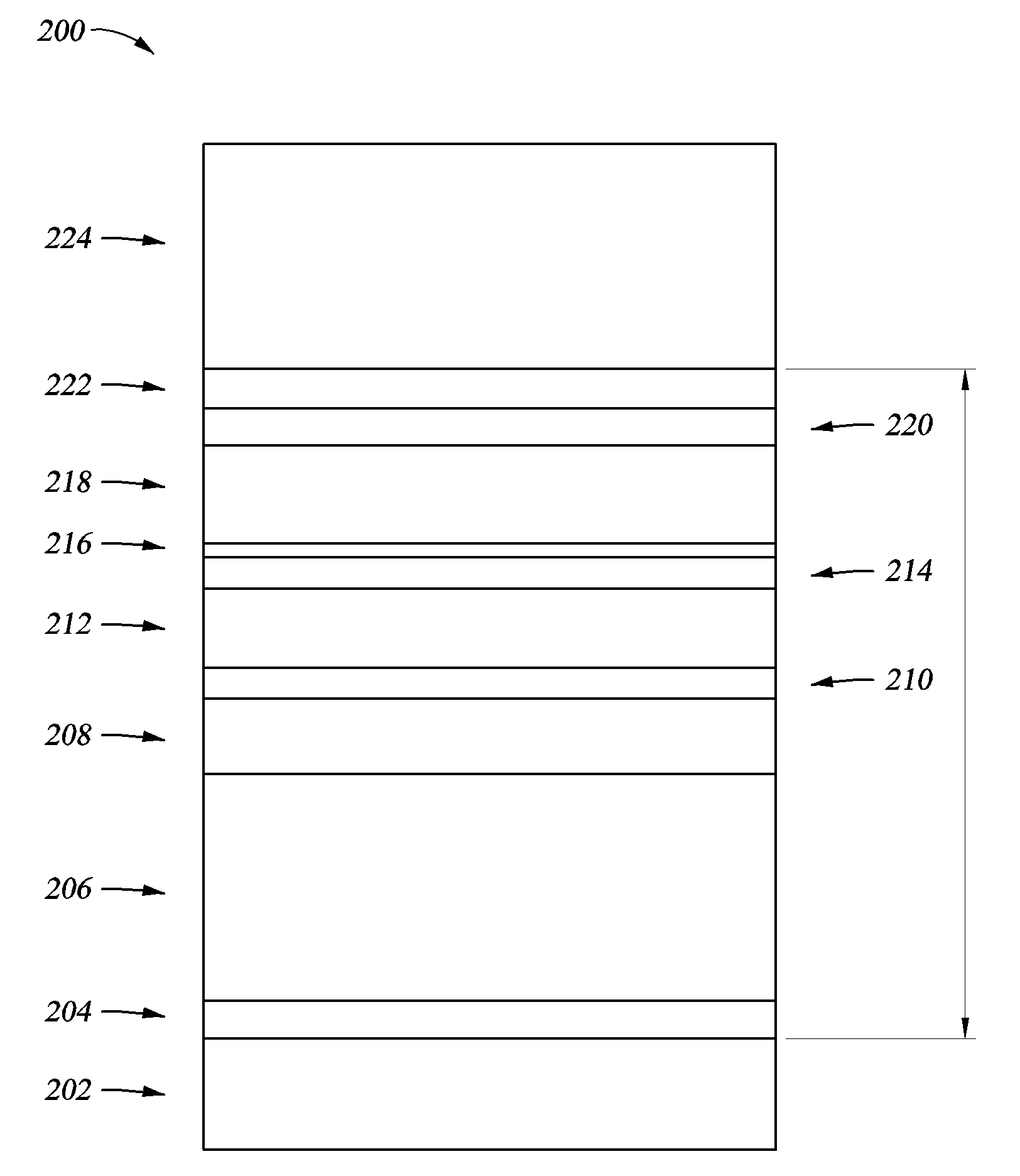
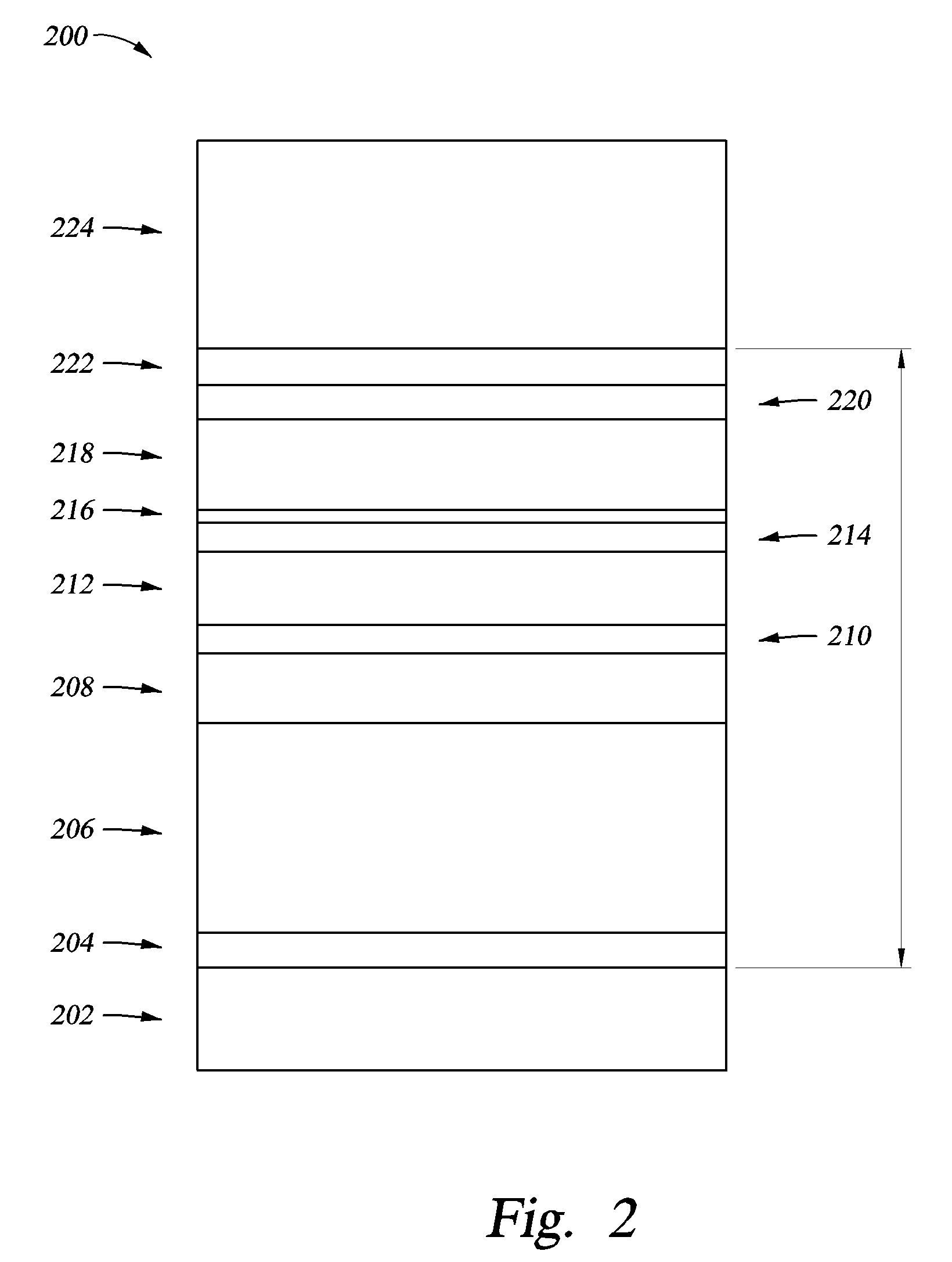
A method, apparatus, and article of manufacture for a current-perpendicular-to-plane (CPP) giant magnetoresistance (GMR) or a tunneling magnetoresistance (TMR) read sensor is proposed. The CPP read sensor comprises an amorphous ferromagnetic first seed layer, a polycrystalline nonmagnetic second seed layer, a nonmagnetic first cap layer, a nonmagnetic second cap layer, and a ferromagnetic third gap layer. A read gap is defined by a distance between the ferromagnetic first seed layer and the ferromagnetic third cap layer.

Description

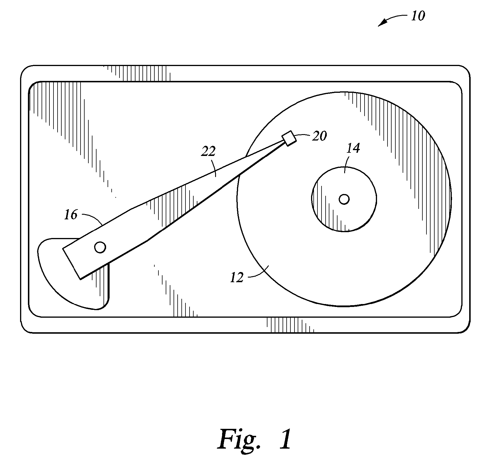
BACKGROUND OF THE INVENTION[0001]1. Field of the Invention[0002]Embodiments of the present invention generally relate to read sensors.[0003]2. Description of the Related Art[0004]A current-in-plane (CIP) giant magnetoresistance (GMR) read sensor has been commonly used for magnetic recording in a storage system. The CIP GMR read sensor is electrically connected with longitudinal bias layers and conducting leads in two side regions. This structure allows a sense current to flow in a direction parallel to the sensor plane. The longitudinal bias layers and conducting leads are electrically separated by lower and upper gap layers from lower and upper shields, respectively, for preventing the sense current from shunting into the lower and upper shields. Shunting occurring when an electric current passes through an unintended path will cause the CIP GMR read sensor to malfunction.[0005]To achieve longitudinal bias stabilization through magnetostatic interactions between the CIP GMR read se...

Claims


Application Information

Patent Timeline
IPC IPC(8): G11B5/33B29C65/00G11B5/39
CPCB82Y10/00B82Y25/00Y10T428/1129G11B5/3929G11B2005/3996G11B5/3909
Inventor LIN, TSANN
Owner HITACHI GLOBAL STORAGE TECH NETHERLANDS BV
Learn More