

Personal environment airflow controller
a controller and airflow technology, applied in the field of air ventilation, filtration, purification, and cleaning, can solve the problems of reducing the air quality of the cabin, affecting the comfort of passengers, and reducing the efficiency of air purification and air cleaning, so as to reduce the pressure suction, increase the air circulation, and reduce the effect of air pressur
- Summary
- Abstract
- Description
- Claims
- Application Information
AI Technical Summary
Benefits of technology
Problems solved by technology
Method used
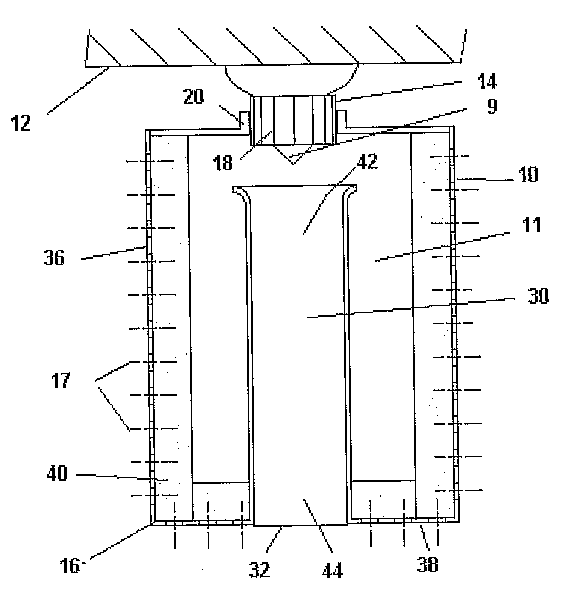
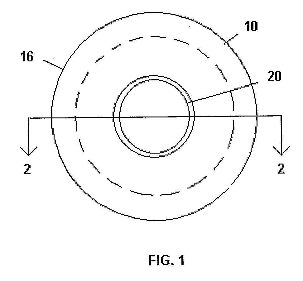
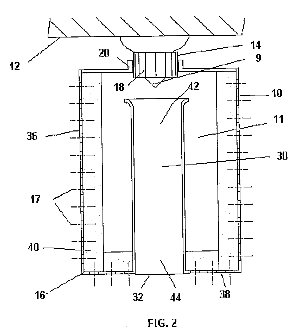
Image

Examples
example 1
[0099]An experiment was performed in which a system similar to that illustrated in FIGS. 12 and 13 was set up to provide an assessment of device parameters on device performance, including:[0100]Device air supply multiplier;[0101]Filter surface area;[0102]Filter particulate removal rate;[0103]Single and multiple air supply jets;[0104]2″ long to 18″ long mixing chambers;[0105]Tubular and conical mixing chambers.
[0106]Air supply jets in front of the mixing chamber versus extending inside the mixing chamber.
[0107]Air was supplied at between 2 inch wc to 10 inch wc pressure into a 1.625″ i.d. tube via one or multiple jets. These jets were created both with 20 holes (total area=0.075 sq. inches) through a flat plate and via a 0.25 inch dia. tube. In the case of the flat plate jets, the plate was spaced away from the 1.625 inch i.d. secondary (mixing) tube at various distances from ¼ inch to a few inches.
[0108]Three mixing chambers were used. Two were tubes, one 2 inches long and the othe...
example 3
[0140]The further example of a CFD model is the built-in version described in connection with FIGS. 7-11 (FIG. 25). There is a single primary 94 feet per second jet orifice 202 with an area Of 0.07069 in2 and a 1.5 inch diameter, 3 inch long mixing chamber. The lower surface and filter have been removed from the view to show the filter dividers 95, fitting 200 and plenum 88.
PUM
| Property | Measurement | Unit |
|---|---|---|
| Length | aaaaa | aaaaa |
| Length | aaaaa | aaaaa |
| Length | aaaaa | aaaaa |
Abstract
Description
Claims
Application Information