Polymeric Pedicle Rods and Methods of Manufacturing

a technology of polymer pedicles and pedicles, applied in the field of polymer pedicles and methods of manufacturing, can solve the problems of adjacent level hypermotion, loosening of the pedicle screw, and reducing postoperative visualization

Active Publication Date: 2009-06-25
DEPUY SYNTHES PROD INC
View PDF103 Cites 169 Cited by
  • Summary
  • Abstract
  • Description
  • Claims
  • Application Information

AI Technical Summary

Benefits of technology

[0008]The present invention involves innovative devices and methods of manufacture of spinal stabilization systems with posterior pedicle rods and pedicle screws. These devices utilize a rod having an internally reinforced polymeric core that is at least partially encased within at least one polymeric coating. The preferred embodiment utilizes a Carbon Fiber-Reinforced PEEK (CFRP) core that is at least partially encased within at least one polymeric coating. The diameter and geometry of the central core and external rod profile can be designed to adjust stiffness in various planes of motion. The core or external rod profile can include ribs to increase support in various planes. The number of carbon fiber layers, the percentage of carbon fiber, and the diameter, construction and planes of fiber orientation can, via various methods of manufacture, be adjusted to further customize rod stiffness in varying planes. These devices can be further grouped into a family and provided as a kit, allowing intra-operative flexibility to select the desired geometry and level of posterior stiffness / constraint supplementation.
[0015]disclose specific PEEK-coated CFRP pedicle rod designs that enhance fatigue endurance and minimize wear at the set screw / rod interface;

Problems solved by technology

Although these systems have been shown to be useful, there has nonetheless been documentation of a number of clinical problems with these systems.
First, there are reports of pedicle screw loosening due to a material stiffness that is significantly higher than that of bone.
There are reports of reduced postoperative visualization due to artifacts incurred with radio-imaging of the metallic components.
Low interbody fusion rates are thought to be due to excessive load transfer through the posterior column, again due to a material stiffness that is significantly higher than that of bone.
Lastly, adjacent level hypermotion, excessive loading and physiological breakdown are also thought to be due to the use of metallic rods.

Method used


Image

  • Polymeric Pedicle Rods and Methods of Manufacturing
  • Polymeric Pedicle Rods and Methods of Manufacturing
  • Polymeric Pedicle Rods and Methods of Manufacturing

Examples


Embodiment Construction

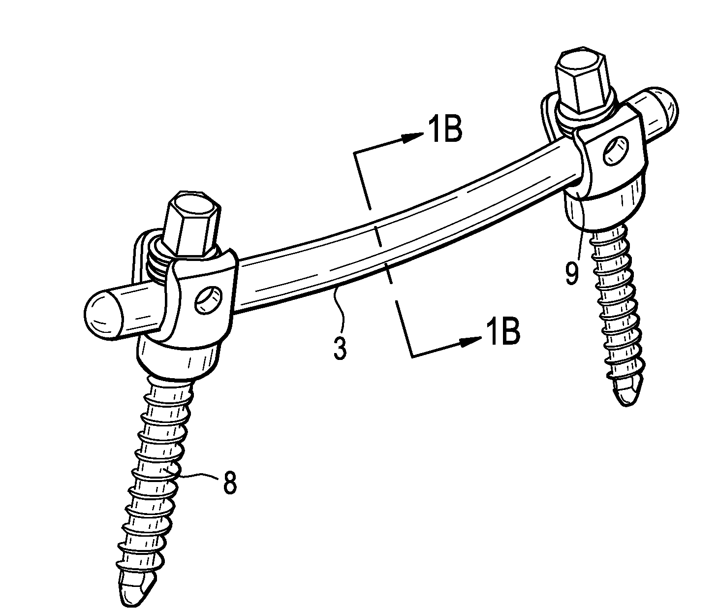
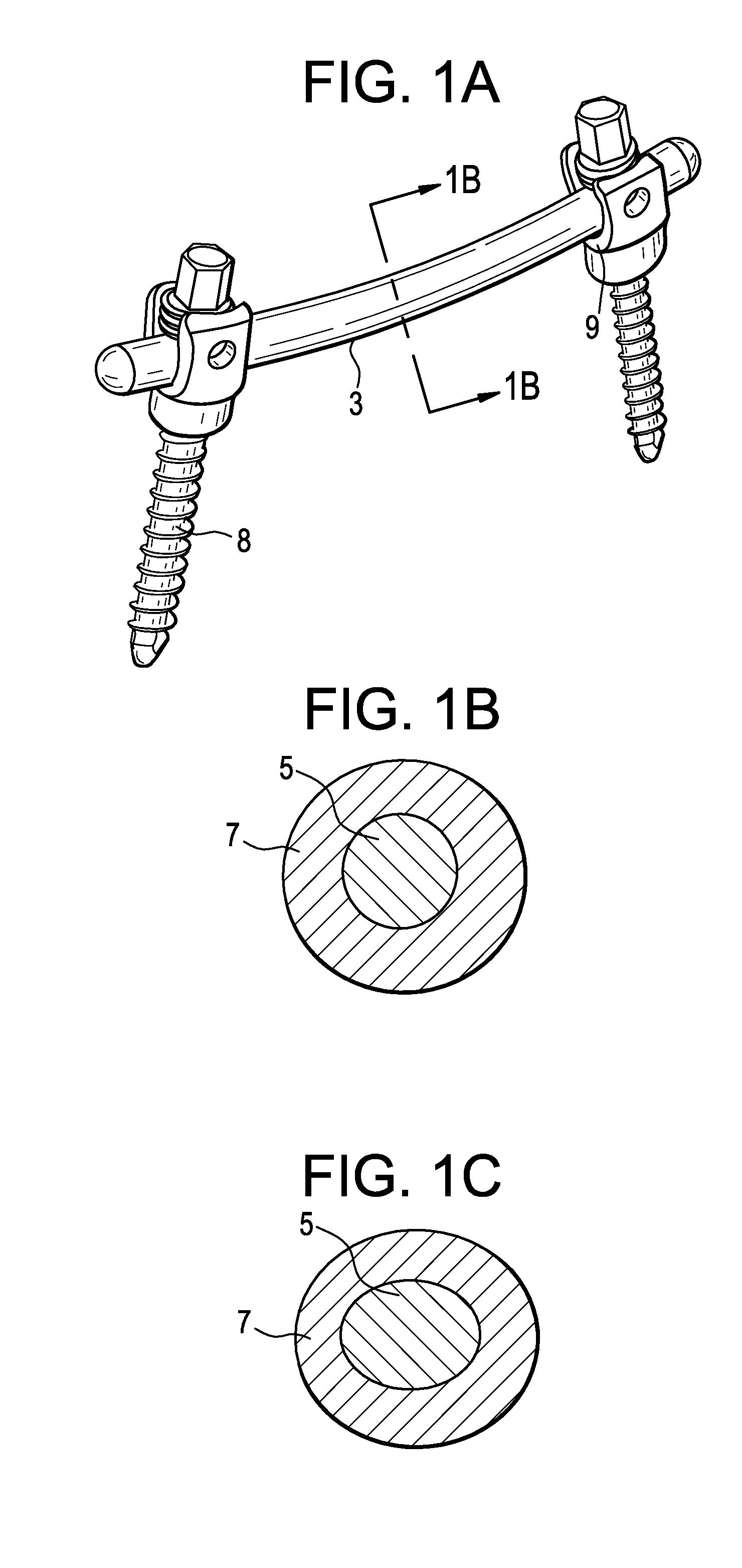
[0041]Now referring to FIGS. 1a-c, there are provided devices utilizing an internally reinforced polymeric core that is at least partially encased within at least one polymeric coating. In particular, there is a spinal fixation assembly 1 comprising:[0042]a) a spinal pedicle rod 3 comprising an internally reinforced polymeric core 5 that is at least partially encased within at least one polymeric coating 7, and[0043]b) a bone anchor 8 having a recess 9 for accepting the rod,

wherein the rod is fixed in the recess of the bone anchor.

[0044]FIG. 1a also shows that the rod may be bent (pre-lordosed) in order to accommodate the curvature of the spine in the region of interest. FIGS. 1b-c disclose axial cross-sections of the rod of FIG. 1a, wherein the rod has an internally reinforced polymeric core 5 that is encased within a polymeric coating 7. Whereas FIG. 1b discloses a circular cross-section, FIG. 1c discloses an oval cross-section. Non-circular cross-sections will provide better stif...


PUM


Abstract

A spinal pedicle rod comprising an internally reinforced polymeric core that is at least partially encased within at least one polymeric coating.A dynamic stabilization device for bones in which flexible rods are combined with a pair of dynamic anchoring devices comprising i) a shank for anchoring into a bone or a vertebra, ii) a head connected to the shank, iii) a receiving part for the head and iv) a mobile element acting on the head.

Description

CONTINUING DATA[0001]This patent application claims priority from co-pending U.S. Provisional Application Ser. No. 61 / 014,851, filed Dec. 19, 2007, entitled “Polymeric Pedicle Rods and Methods of Manufacturing, (Attorney Docket No. DEP6072USPSP).BACKGROUND OF THE INVENTION[0002]Metallic-based pedicle rod and screw systems are often used in spinal surgeries to correct spinal deformities and intervertebral disc degeneration. Although these systems have been shown to be useful, there has nonetheless been documentation of a number of clinical problems with these systems. First, there are reports of pedicle screw loosening due to a material stiffness that is significantly higher than that of bone. There are reports of reduced postoperative visualization due to artifacts incurred with radio-imaging of the metallic components. Low interbody fusion rates are thought to be due to excessive load transfer through the posterior column, again due to a material stiffness that is significantly hig...

Claims


Application Information

Patent Timeline
Patent Type & Authority Applications(United States)
IPC IPC(8): A61B17/70
CPCA61B17/701A61B17/7011A61B2017/00526A61B17/7037A61B17/7031
Inventor MOUMENE, MISSOUMFANGER, JONATHANBARTISH, JR., CHARLES M.O'NEIL, MICHAEL J.UPAL, ANWARCONNOLLY, STEPHENHAWKINS, JOHN RILEYSLIVKA, MICHAEL A.
Owner DEPUY SYNTHES PROD INC
Why Eureka
Try Eureka