Method And Apparatus Using Aiming Pattern For Machine Vision Training

Active Publication Date: 2009-07-02
COGNEX CORPORATION
View PDF38 Cites 23 Cited by
  • Summary
  • Abstract
  • Description
  • Claims
  • Application Information

AI Technical Summary

Benefits of technology

[0011]It has been recognized that a simple aiming device that is separate from a reader can be provided that can generate an illumination aiming pattern on a feature or area of interest on an object so that when an image of the object including the aiming pattern is captured, the pattern can be recognized within the captured image and processing associated therewith can be performed on the feature or area of interest. For example, in the case of a training commissioning procedure, a hand held laser aim

Problems solved by technology

In early inspection systems object features of interest had to be manually programmed which was complicated and time consuming.
Unfortunately many inspection systems do not include an output device such as a displa

Method used


Image

  • Method And Apparatus Using Aiming Pattern For Machine Vision Training
  • Method And Apparatus Using Aiming Pattern For Machine Vision Training
  • Method And Apparatus Using Aiming Pattern For Machine Vision Training

Examples


Embodiment Construction

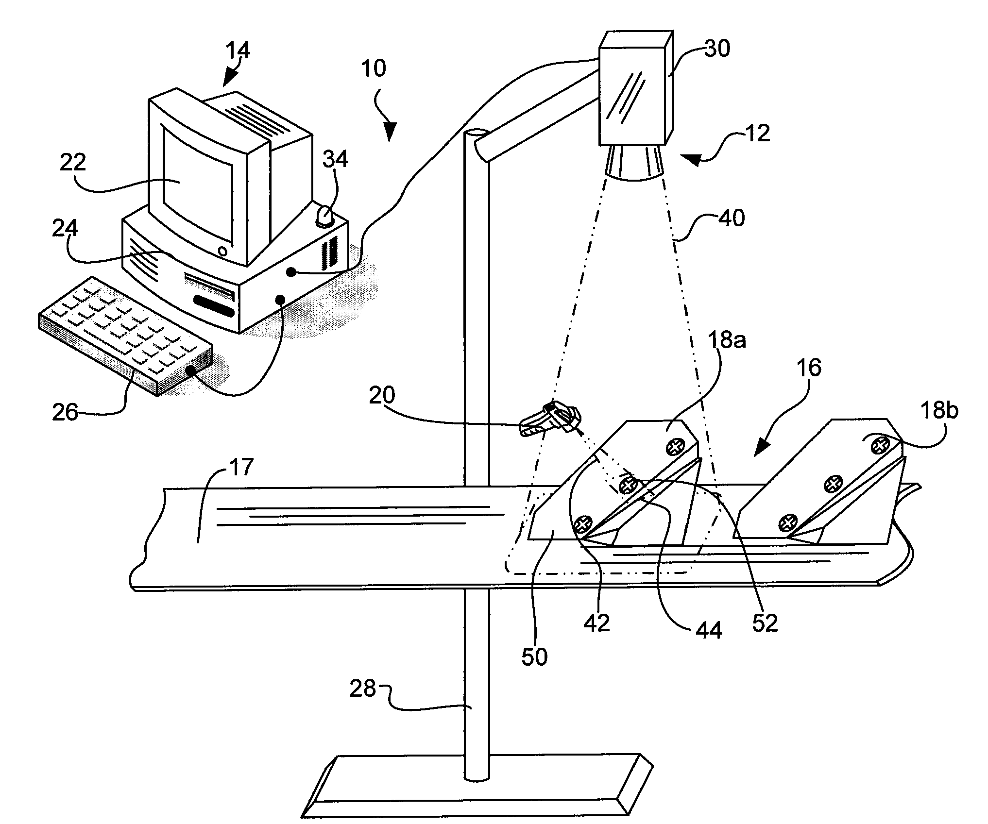
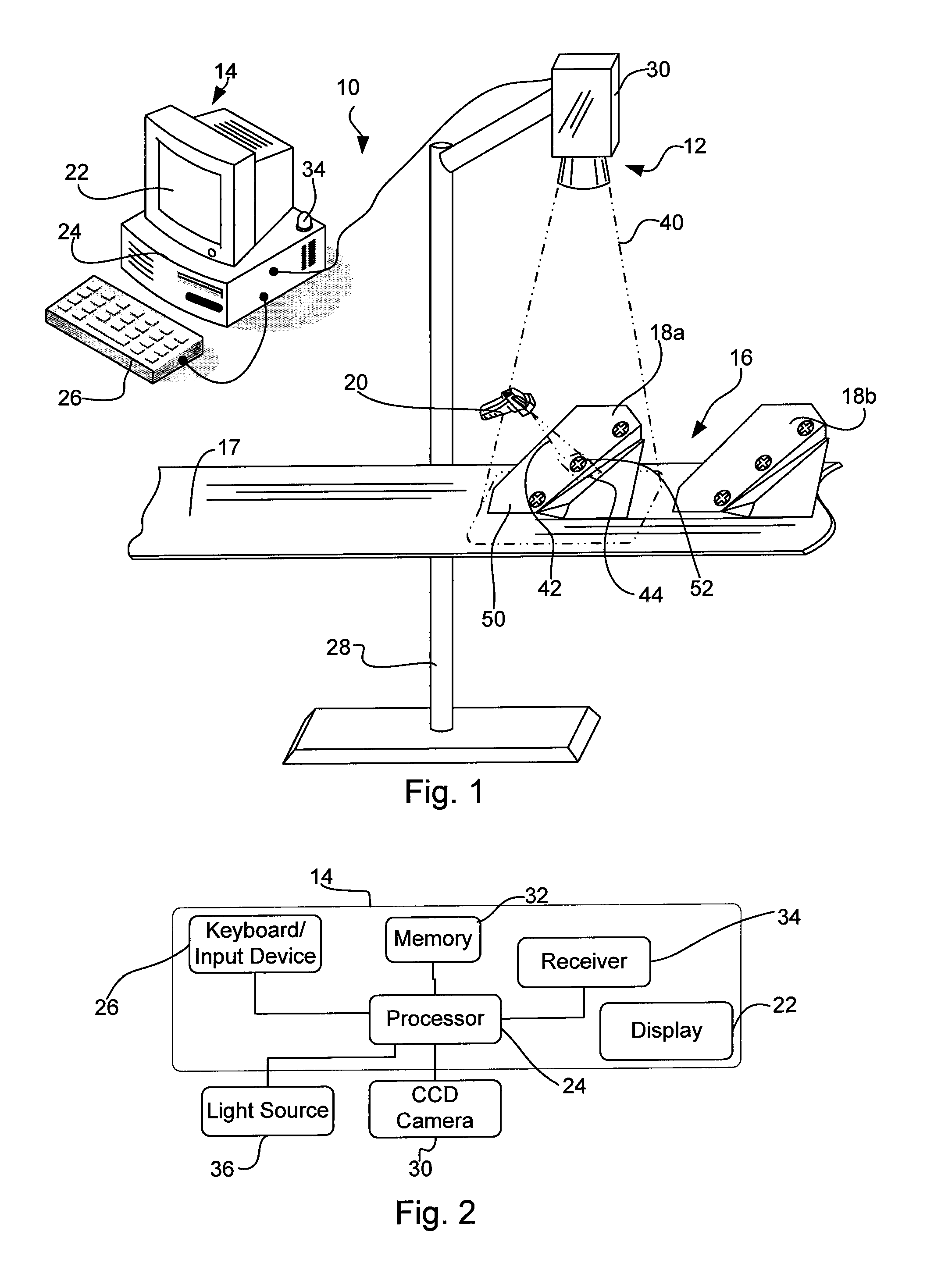
[0046]Referring now to the drawings wherein like reference numerals correspond to similar elements throughout the several views and, more specifically referring to FIG. 1, the present invention will be described in the context of an exemplary object imaging system 10 including a camera 12, a workstation 14, a transfer line 16, a plurality of objects to be imaged, two of which are identified by 18a and 18b, and a handheld aiming device 20. Referring also to FIG. 2, workstation 14 includes a display 22, a processor 24, a keyboard / input device 26, a memory 32 and a receiver 34. Processor 24 is linked to each of the display 22, keyboard 26, memory 32 and receiver 34. Programs run by processor 24 are stored in memory 32. Processor 24 provides output to a system user via a display 22. Processor 24 receives user input via the keyboard input device 26 and can also receive wireless transmissions via receiver 34. Receiver 34 is akin to an access point in a wireless network or the like.

[0047]R...


PUM


Abstract

A method and apparatus for use with a camera that includes a field of view (FOV), the method for selecting a portion of the field of view for analysis and comprising the steps of placing at least a portion of a first object within the field of view of the camera, providing a light source separate from the camera, directing the light source toward the first object within the field of view of the camera so that the light forms an aiming pattern that is one of on and proximate a first location of interest on the first object, obtaining an image of the portion of the first object within the field of view including the aiming pattern, identifying the location of the aiming pattern in the obtained image and using the aiming pattern in the obtained image to perform a processing function.

Description

CROSS-REFERENCE TO RELATED APPLICATIONS[0001]Not applicable.STATEMENT REGARDING FEDERALLY SPONSORED RESEARCH OR DEVELOPMENT[0002]Not applicable.BACKGROUND OF THE INVENTION[0003]The present invention relates to machine vision systems and more specifically to a system wherein an aiming pattern can be generated and directed at an area or feature on an object to be imaged to select the feature or object for enhanced analysis.[0004]Machine vision systems have been developed for use in automated inspection systems that capture images of objects within a field of view and examine the objects to determine if the objects have expected features. Where expected features are not present, in some cases the objects are rejected, in other cases an automated process may have to be halted and in still other cases objects have to be reoriented. In early inspection systems object features of interest had to be manually programmed which was complicated and time consuming.[0005]More recent inspection sy...

Claims


Application Information

Patent Timeline
IPC IPC(8): G06K7/10
CPCG06F3/0317G06K2207/1011G06K7/10792G06K7/10722G06F3/0304G06F3/0386
Inventor GERST, CARL W.SCHATZ, DAVID
Owner COGNEX CORPORATION
Why Eureka
Try Eureka