Aircraft arrestor system and method of decelerating an aircraft

a technology of aircraft arrestor and aircraft, which is applied in the direction of anchoring installation, anchoring hook, alighting gear, etc., can solve the problems of increasing the chance of damage to passengers, aircraft, airports, pedestrians or other persons, and lack of space required to provide sufficient safety areas, etc., to achieve the effect of improving drainage characteristics

Active Publication Date: 2009-07-02
TARKETT INC
View PDF41 Cites 16 Cited by
  • Summary
  • Abstract
  • Description
  • Claims
  • Application Information

AI Technical Summary

Benefits of technology

[0004]It is an object of the present invention to provide an arrestor system that will have improved drainage characteristics.

Problems solved by technology

Aircraft can and do overrun the ends of the runways and taxiways at airports which may increase the chance of damage to passengers, the aircraft, the airport and / or pedestrians or other persons.
While there is typically provided a safety area at the ends of the runways, some airports lack the space required to provide sufficient safety areas.
While presumably effective for their intended purposes, the patents related to cellular concrete disclose that obtaining an appropriate cellular concrete with sufficient strength can be difficult.
Additionally, the device disclosed in U.S. Pat. No. 3,066,896 discloses a cover for the arrestor bed that may be considered aesthetically unpleasing.

Method used


Image

  • Aircraft arrestor system and method of decelerating an aircraft
  • Aircraft arrestor system and method of decelerating an aircraft
  • Aircraft arrestor system and method of decelerating an aircraft

Examples


Embodiment Construction

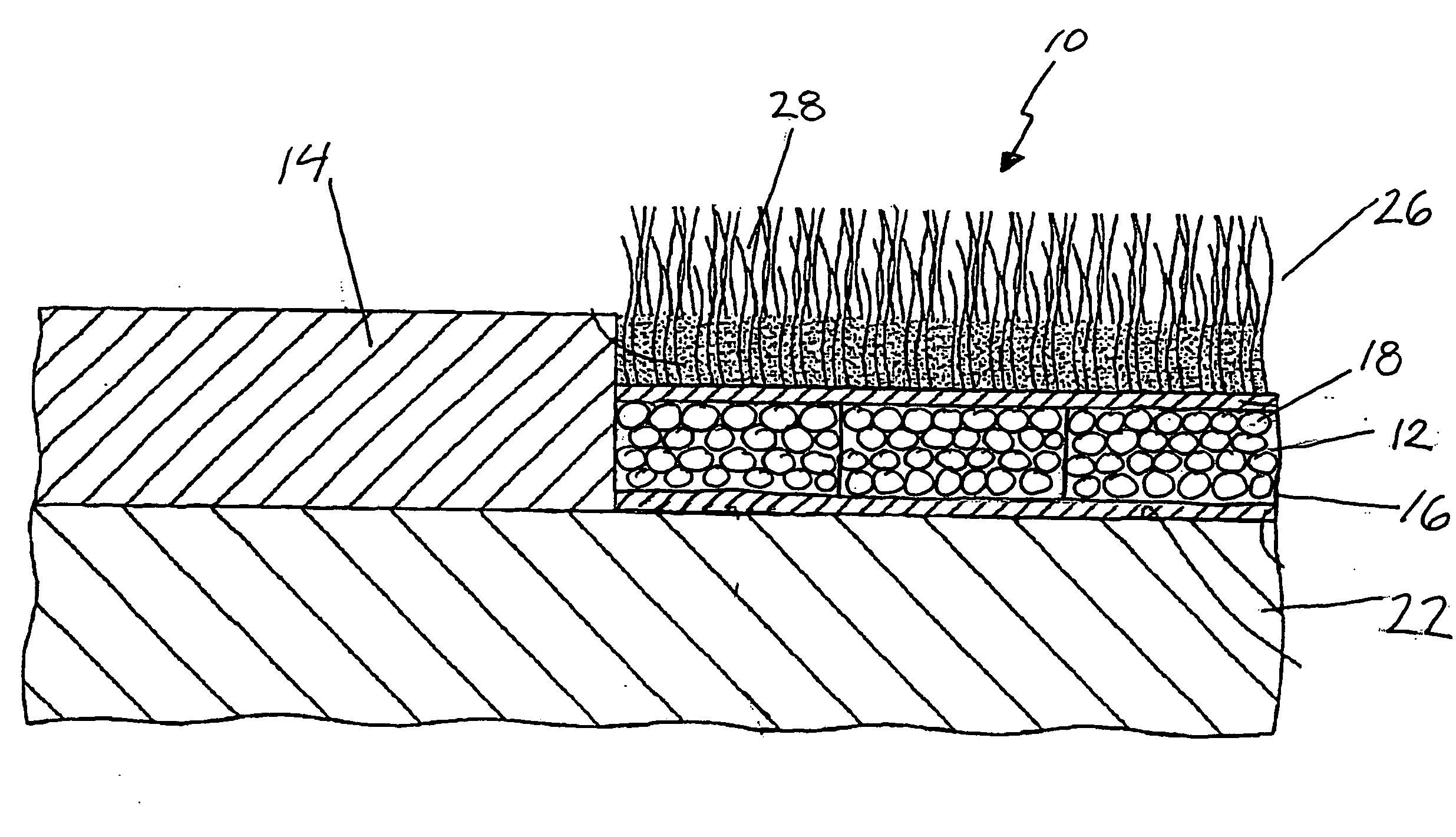
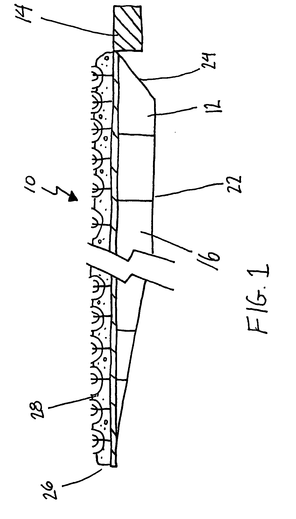
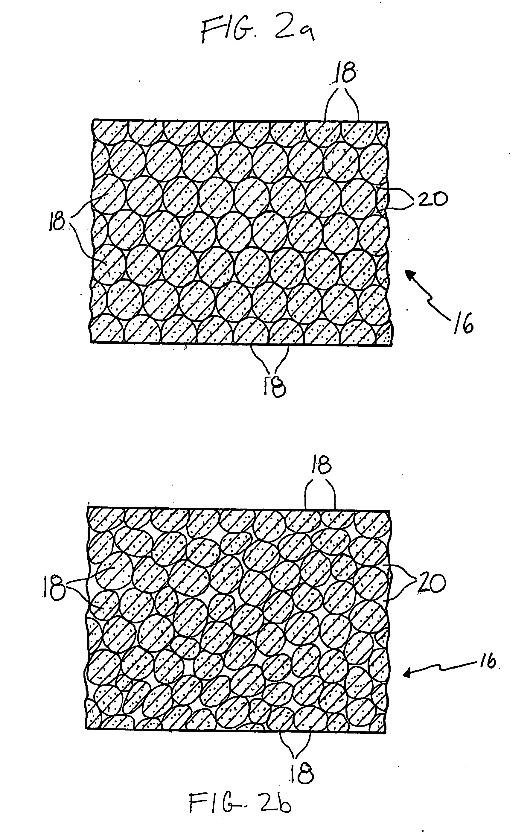
[0012]Having thus generally described the nature of the invention, reference will now be made to the accompanying drawings, showing by way of illustration a preferred embodiment thereof. FIG. 1 illustrates an aircraft arrestor system 10 comprising a base 12 located adjacent a runway 14. The base 12 has at least one tile 16 comprised of a plurality of particles 18 being arranged such that the particles 18 form a plurality of water drainage passageways 20. These types of tiles 16 have been used as a base in sports fields with synthetic grass systems and are disclosed in U.S. Pat. No. 7,244,477. The particles 18 may be substantially spherically shaped (FIG. 2a) and / or they may be substantially equally sized. Alternatively, the particles 18 may be differently shaped (FIG. 2b). Moreover, the tile 16 may further include a binding agent, which is known to those of ordinary skill in the art.

[0013]The tile 16 has a compressive strength which will fatigue upon a force greater than its compres...


PUM


Abstract

An arrestor system and method of decelerating an aircraft. The arrestor system has a base with at least one tile made of a plurality of particles being arranged such that the particles form a plurality of water drainage passageways and wherein the at least one tile has a compressive strength which will fatigue upon a force being imparted thereto which is greater than the compressive strength of the tile.

Description

[0001]The present invention relates generally to aircraft arrestor systems and methods of decelerating an aircraft, and more particularly to a base to be used in an arrestor system.BACKGROUND OF THE INVENTION[0002]Aircraft can and do overrun the ends of the runways and taxiways at airports which may increase the chance of damage to passengers, the aircraft, the airport and / or pedestrians or other persons. While there is typically provided a safety area at the ends of the runways, some airports lack the space required to provide sufficient safety areas.[0003]One device that has been utilized to provide assistance in decelerating an aircraft is an arrestor system. U.S. Pat. No. 3,066,896 issued to Schirtzinger discloses such a device. Additionally, the following patents disclose similar arrestor systems and / or a cellular concrete to be used in an arrestor system: U.S. Pat. Nos. 5,885,025; 5,902,068; 6,726,400; 6,685,387; 6,971,817. While presumably effective for their intended purpose...

Claims


Application Information

Patent Timeline
Patent Type & Authority Applications(United States)
IPC IPC(8): B64F1/02
CPCB64F1/025B64F1/02
Inventor PREVOST, JEANVANDYKE, DONALD
Owner TARKETT INC
Why Eureka
Try Eureka