
Light-emitting diode structure

a technology of light-emitting diodes and leds, which is applied in the direction of semiconductor devices, printed circuit aspects, solid-state devices, etc., can solve the problems of troublesome and inconvenient mounting of conventional leds to power supply boards, unfavorable disassembly or replacement of conventional leds, etc., and achieves convenient replacement and mounting. easy

Inactive Publication Date: 2009-07-02
PACIFIC SPEED
View PDF2 Cites 13 Cited by
  • Summary
  • Abstract
  • Description
  • Claims
  • Application Information

AI Technical Summary

Benefits of technology

"The present invention provides an LED structure that can be easily mounted and dismounted from a power supply board, making it convenient to replace when necessary. The LED structure includes a first conductive body, a first insulating body, and a second conductive body. The first conductive body has an upward projected conducting portion, while the first insulating body has an insulating sleeve portion fitted around the conducting portion, exposing the conducting section at the top of the conducting portion. The second conductive body has a through opening, and the insulating sleeve portion of the first insulating body is extended through the opening to electrically isolate the second conductive body from the first conductive body. The LED has at least one first electrode in electric contact with the conducting section of the first conductive body and at least one second electrode in electric contact with the second conductive body. This LED structure allows for easy replacement and convenient maintenance of the LED."

Problems solved by technology

Therefore, the mounting of the conventional LED to a power supply board is troublesome and inconvenient.
Similarly, it is uneasy to dismount or replace the conventional LED when the same is failed.

Method used


Image

  • Light-emitting diode structure
  • Light-emitting diode structure
  • Light-emitting diode structure

Examples


Embodiment Construction

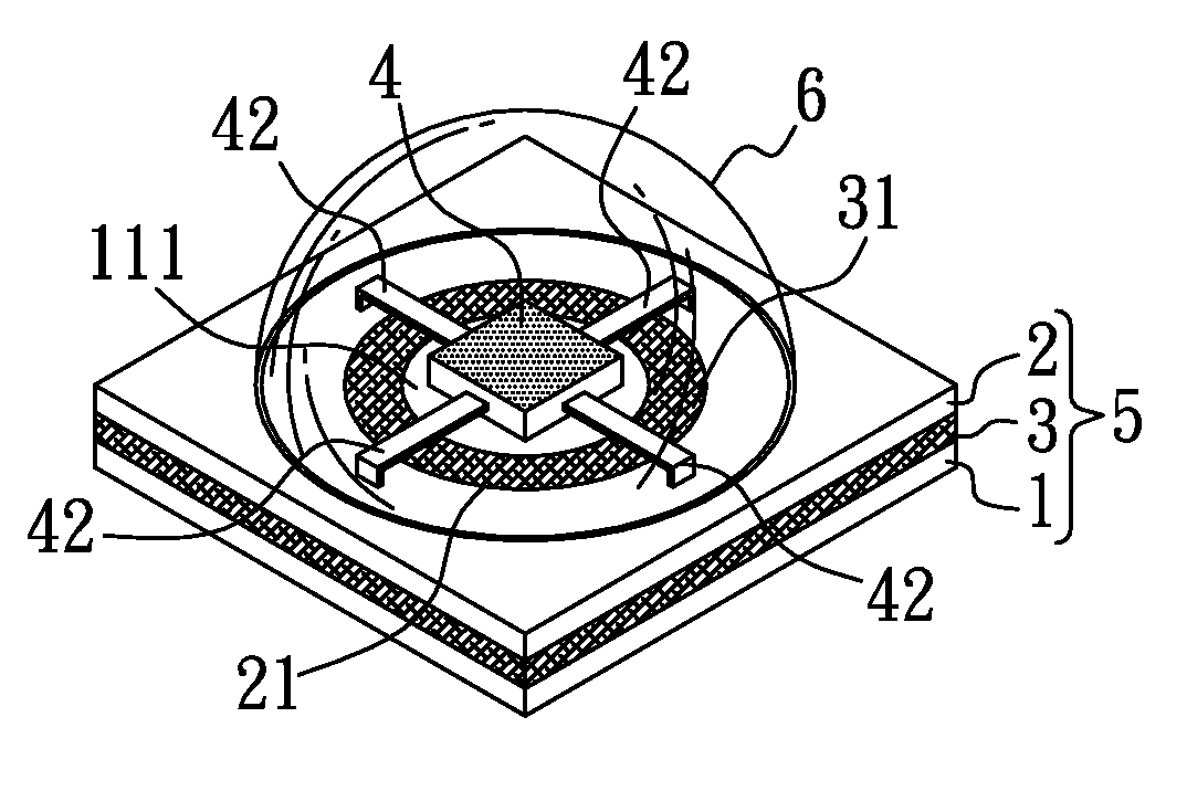
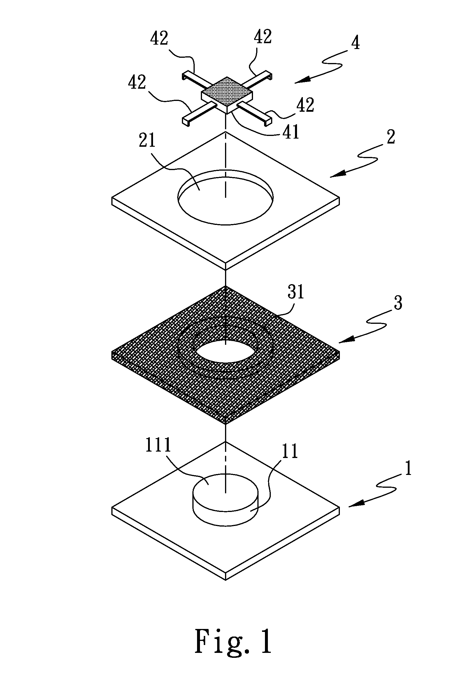
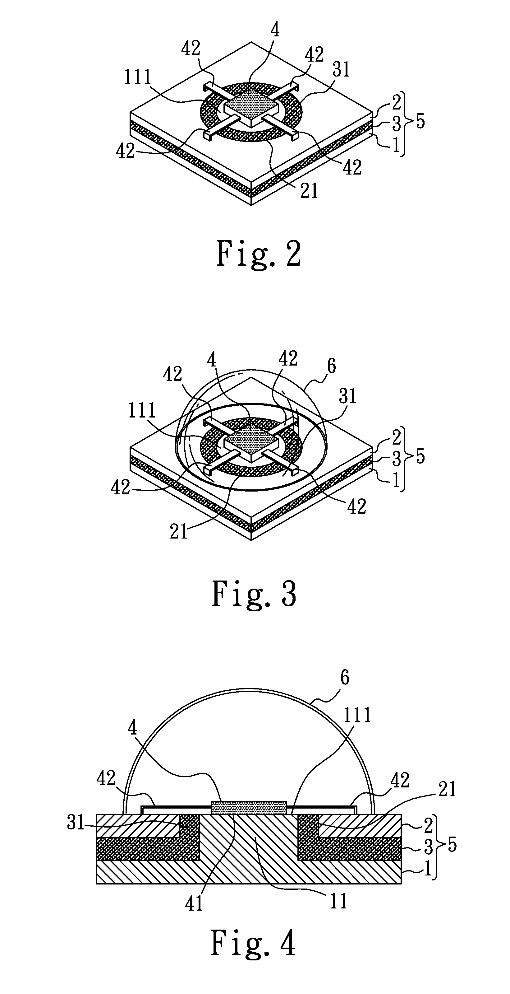
[0030]Please refer to FIGS. 1 and 2 that are exploded and assembled perspective views, respectively, of an LED structure according to a first preferred embodiment of the present invention. As shown, in the first preferred embodiment, the LED structure includes a first conductive body 1, a second conductive body 2, a first insulating body 3, and an LED 4.

[0031]The first conductive body 1 includes an upward projected conducting portion 11, which may be a cylindrical post.

[0032]The first insulating body 3 includes an insulating sleeve portion 31, which may be a hollow boss, such that the first insulating body 3 may be disposed on the first conductive body 1 with the insulating sleeve portion 31 fitted around the upward projected conducting portion 11. It is noted a conducting section 111 at a top of the projected conducting portion 11 is exposed at the sleeve portion 31.

[0033]The second conductive body 2 includes a through opening 21 and is disposed on the first insulating body 3, such...


PUM


Abstract

An LED structure includes a first conductive body, a first insulating body on the first conductive body, a second conductive body on the first insulating body, and an LED. The first conductive body has a conducting portion upward projected from the insulating body and the second conductive body, so that a conducting section at a top of the conducting portion is exposed at the insulating sleeve portion. The LED is mounted on the conducting section of the first conductive body and electrically connected to the second conductive body. With these arrangements, the LED structure may be mounted on a power supply board without the need of distinguishing the polarities of electrodes, and can therefore be easily mounted to and dismounted from the power supply board and be conveniently replaced when necessary.

Description

FIELD OF THE INVENTION[0001]The present invention relates to a light-emitting diode (LED) structure, and more particularly to an LED structure that could be easily mounted to and dismounted from a power supply board and therefore be conveniently replaced when necessary.BACKGROUND OF THE INVENTION[0002]A light-emitting diode (LED) has the advantages of having simple structure and providing high brightness, and is therefore widely employed in advertising and illuminating facilities, such as large-scaled outdoor TV walls, large-scaled outdoor signboards, car lights, flashlights, etc. Conventionally, the LED has a longer and a shorter pin, and the two pins have different polarities. To mount the conventional LED to a power supply board, a user has to check whether two insertion holes on the power supply board for receiving the two pins of the LED respectively have a polarity the same as that of the pin to be received therein. If not, the user has to turn the LED for the pins thereof to ...

Claims


Application Information

Patent Timeline
Patent Type & Authority Applications(United States)
IPC IPC(8): H01L33/00H01L33/62
CPCH01L33/62H05K1/184H05K2201/09309H05K2201/10106H01L2924/0002H01L2924/00
Inventor LIN, CHIEN-FENG
Owner PACIFIC SPEED
Learn More