Sheet-Discharging Apparatus for Sheet-Fed Printing Press

a technology of sheet-fed printing press and discharging apparatus, which is applied in the directions of transportation and packaging, thin material processing, and article delivery, etc., can solve the problems of inability to carry out cleaning operation of fan device, inability to easily remove flour or powder accumulated on the upper surface of the bracket, and inability to see the operator (personnel) easily, so as to improve the safety of the operator and facilitate the cleaning operation of the fan device. , the effect of improving the operator

Inactive Publication Date: 2009-07-02
MITSUBISHI HEAVY IND LTD
View PDF3 Cites 5 Cited by
  • Summary
  • Abstract
  • Description
  • Claims
  • Application Information

AI Technical Summary

Benefits of technology

[0008]In view of such problems, it is an object of the present invention to provide a sheet-discharging apparatus for a sheet-fed printing press in which a fan device is downsized, the visibility of the operator is improved, the cleaning operation of the fan device is carried out easily, and the blast fan may be shifted easily and quickly to a desired position according to the size or the material of the sheet to be printed.
[0024]According to the present invention, there are effects that the fan device is downsized, the visibility of the operator is improved, the cleaning operation of the fan device is facilitated, and the blast fans may be shifted easily and quickly to desired positions according to the size or the material of the sheet to be printed.

Problems solved by technology

Therefore, the dimension of the fan device in the direction of height is increased, so that there arises a problem that the fan device is upsized, and hence visibility of an operator (personnel) is blocked.
Since the bracket has a complicated shape, dust such as paper flour or powder accumulated on the upper surface of the bracket cannot be removed easily, so that there is also a problem that the cleaning operation of the fan device cannot be carried out easily.
Furthermore, since the bracket to which the blast fan is attached is firmly fixed to the suspending bar via, for example, a fastening member such as a bolt & nut, there arises a problem that the blast fan cannot be shifted easily and quickly to desired positions according to the size or the material of the sheet to be printed, so that it requires long time for an adjustment work.

Method used


Image

  • Sheet-Discharging Apparatus for Sheet-Fed Printing Press
  • Sheet-Discharging Apparatus for Sheet-Fed Printing Press
  • Sheet-Discharging Apparatus for Sheet-Fed Printing Press

Examples


first embodiment

[0058]Referring now to FIG. 1 to FIG. 4, a sheet-discharging apparatus for a sheet-fed printing press according to the present invention will be described.

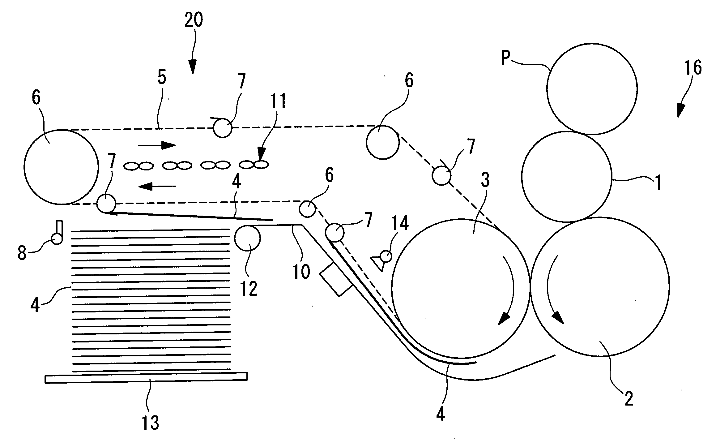
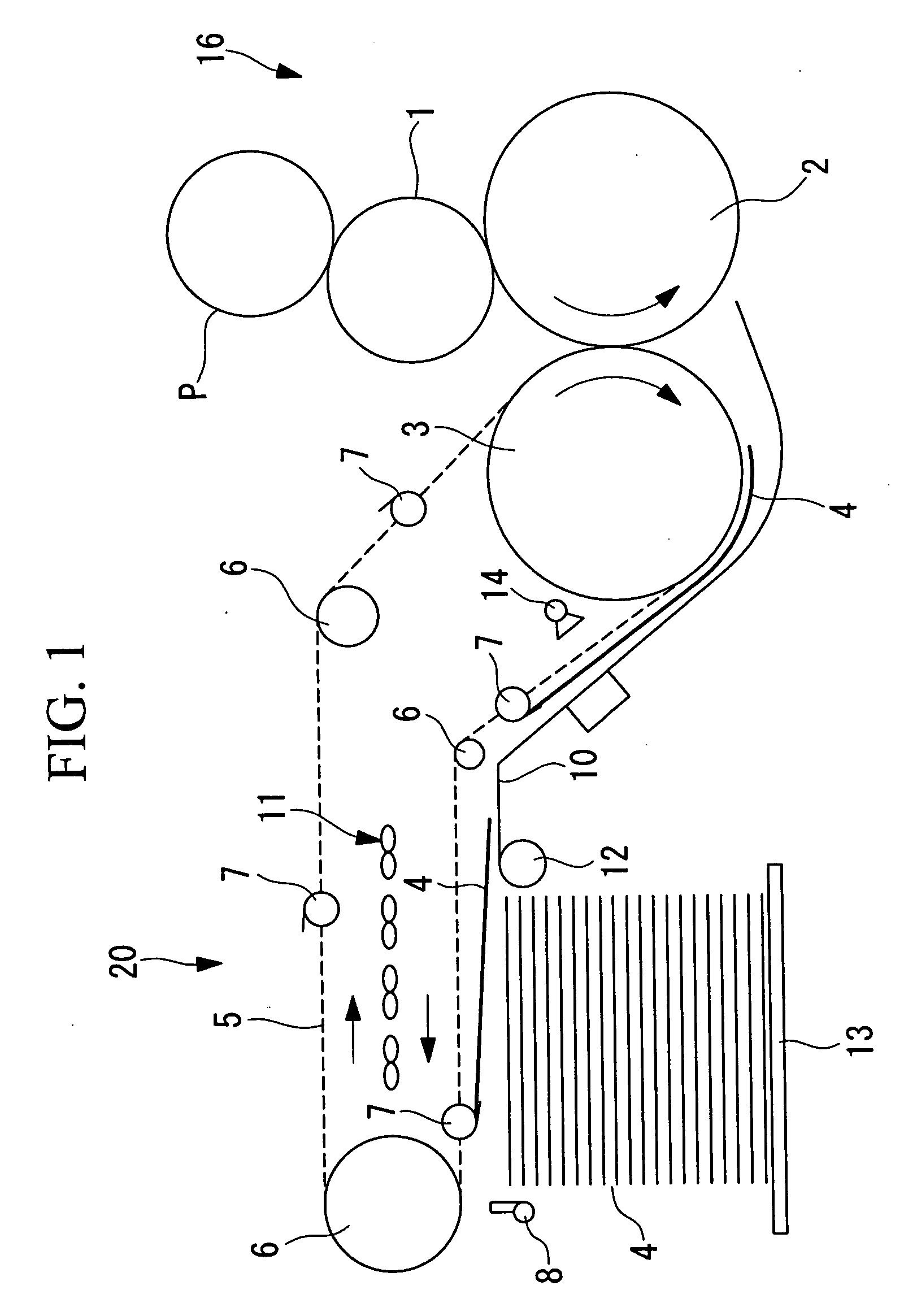
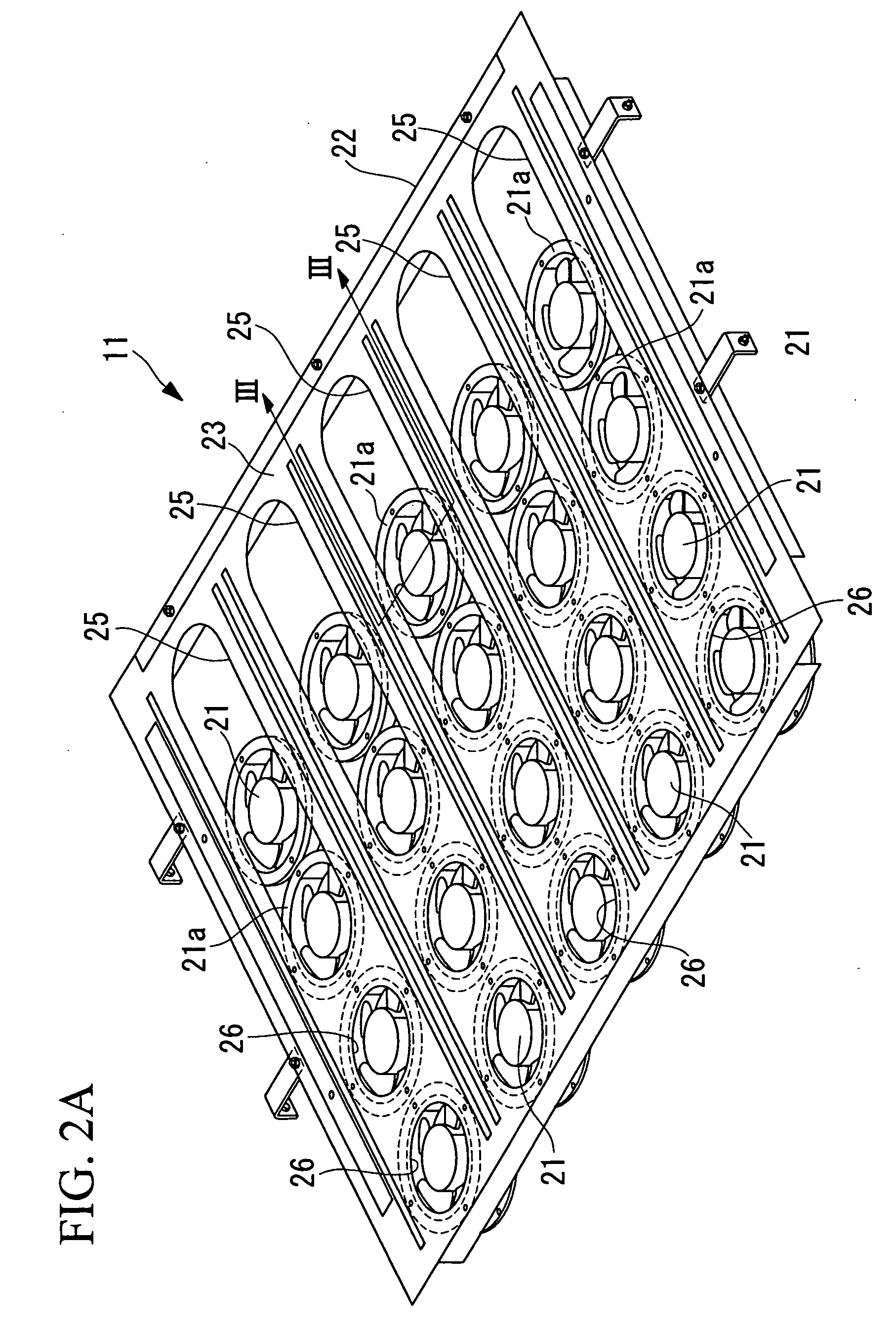
[0059]FIG. 1 is a general schematic block diagram of a sheet-fed printing press 100 provided with a sheet-discharging apparatus 20 for a sheet-fed printing press (hereinafter, referred to simply as “sheet-discharging device”), FIG. 2A and FIG. 4 are general perspective views of a fan device 11 shown in FIG. 1, FIG. 2B is a front view of the fan device 11 shown in FIG. 2A viewed from the lower left side of the drawing, and FIG. 3 is a cross-sectional view taken along the line III-III in FIG. 2A.

[0060]As shown in FIG. 1, the sheet-fed printing press 100 includes a sheet-feeding device (not shown), a printing apparatus 16 and the sheet-discharging apparatus 20.

[0061]The sheet-feeding device is a unit configured to allow sheets (for example, printing sheets) 4 as printed material to be stacked on a sheet-feeding table (not shown), and...

second embodiment

[0081]Referring now to FIG. 5, the sheet-discharging apparatus according to the present invention will be described.

[0082]The sheet-discharging apparatus in this embodiment is different from that in the first embodiment in that a fan device 31 including a plurality (five in this embodiment) of third openings 30 is provided instead of the fan device 11 having the second openings 26 and the second openings 26. Since other components are the same as those in the first embodiment, description of these components will be omitted here.

[0083]The third openings 30 are formed in an elongated shape so as to extend along the feeding direction from the upstream side to the downstream side of the frame body 23. The plurality of third openings 30 are arranged in line in the widthwise direction (the direction orthogonal to the feeding direction).

[0084]On the other hand, a plurality (ten in this embodiment) of the slide rails 24 (see FIG. 3) extending in the feeding direction along the both lateral...

third embodiment

[0088]Referring now to FIG. 6, the sheet-discharging apparatus in the present invention will be described.

[0089]The sheet-discharging apparatus in this embodiment is different from that in the first embodiment described above in that a fan device 41 having the first openings 25 and a plurality of (two in this embodiment) fourth openings 40 is provided instead of the fan device 11 having the first openings 25 and the second openings 26. Since other components are the same as those in the first embodiment, description of these components will be omitted here.

[0090]Although only one each of the blast fan 21 is drawn in the fourth openings 40 in FIG. 6, it is just for simplification of the drawing and, in practice, there are provided a plurality of (four, for example) blast fans 21, in each of the fourth openings 40.

[0091]The fourth openings 40 are formed in an elongated shape so as to extend along the widthwise direction from one side to the other side of the frame body 23. The plurali...


PUM


Abstract

To provide a sheet-discharging apparatus for a sheet-fed printing press in which a fan device is downsized, the visibility of an operator is improved, cleaning operation of the fan device is carried out easily, and a blast fan may be shifted easily and quickly to a desired position according to the size or the material of a sheet to be printed. There is provided a sheet-discharging apparatus for a sheet-fed printing press including: a fan device having a plurality of blast fans and a frame for mounting the blast fans, in which at least some of the plurality of blast fans are arranged in contact with the lower surface of a frame body corresponding to elongated openings formed on the thin-plate shaped frame body which constitutes the frame, and are slidable in the feeding direction and / or in the widthwise direction with respect to the frame body.

Description

RELATED APPLICATIONS[0001]The present application is based on, and claims priority from, Japanese Application Number 2006-093346, filed Mar. 30, 2006, the disclosure of which is hereby incorporated by reference herein in its entirety.TECHNICAL FIELD[0002]The present invention relates to a sheet-discharging apparatus for a sheet-fed printing press.BACKGROUND ART[0003]As a sheet-discharging apparatus for a sheet-fed printing press, for example, the one disclosed in Patent Citation 1 is known.[0004]Patent Citation 1: Japanese Unexamined Patent Application Publication No. 2002-234654DISCLOSURE OF INVENTION[0005]The sheet-discharging apparatus for a sheet-fed printing press disclosed in Patent Citation 1 is provided with a fan device having a plurality of blast fans above a sheet-discharging table. Each blast fan is suspended and supported by a suspending bar extending between frames via a specific bracket having a thickness in the direction of height (vertical direction). Therefore, the...

Claims


Application Information

Patent Timeline
Patent Type & Authority Applications(United States)
IPC IPC(8): B65H29/24
CPCB65H29/041B65H2801/21B65H2406/12B65H29/247
Inventor MIWA, TOSHIOSATO, NOBUTAKA
Owner MITSUBISHI HEAVY IND LTD
Why Eureka
Try Eureka