Strobed headlight for improved visibility

a headlight and strobe technology, applied in the field of strobe lights, can solve the problems of further reducing visibility under many conditions, and achieve the effects of improving operator visibility, reducing or eliminating the perceived streaking of precipitation or debris, and improving operator visibility

Active Publication Date: 2015-07-14
ARROW ELECTRONICS
View PDF4 Cites 1 Cited by
  • Summary
  • Abstract
  • Description
  • Claims
  • Application Information

AI Technical Summary

Benefits of technology

[0006]A light providing improved visibility during adverse conditions includes an array of discrete lights distributed over a surface. The discrete lights are configured to distribute directional light over a three-dimensional space. A regulation and multiplexing circuit is coupled to the array of discrete lights and configured to power discrete lights such that the regulation and multiplexing circuit strobes the discrete lights in accordance with environmental conditions to reduce or eliminate perceived streaking of precipitation or debris to improve operator visibility.
[0007]A strobing light system providing improved visibility during adverse conditions includes at least one light including an array of discrete lights distributed over a surface, the discrete lights being configured to distribute directional light over a three-dimensional space. A controller is responsive to an input to enable a lighting mode. A regulation and multiplexing circuit is coupled to the array of discrete lights and configured to power discrete lights in accordance with the lighting mode such that the regulation and multiplexing circuit strobes the discrete lights in accordance with environmental conditions to reduce or eliminate perceived streaking of precipitation or debris to improve operator visibility.
[0008]A method for improving visibility during adverse conditions includes providing at least one light including an array of discrete lights distributed over a surface, the discrete lights being configured to distribute directional light over a three-dimensional space; enabling a lighting mode in accordance with environmental conditions; and regulating energy to discrete lights in the array of discrete lights in accordance with the lighting mode and characteristic of the environmental conditions such that the discrete lights are strobed in a plurality of directions to reduce or eliminate perceived streaking of precipitation or debris to improve operator visibility.

Problems solved by technology

Attempts to improve visibility have included wipers for the headlights, fog lights, if available, and high beams, which can even further reduce visibility under many conditions.

Method used


Image

  • Strobed headlight for improved visibility
  • Strobed headlight for improved visibility
  • Strobed headlight for improved visibility

Examples


Embodiment Construction

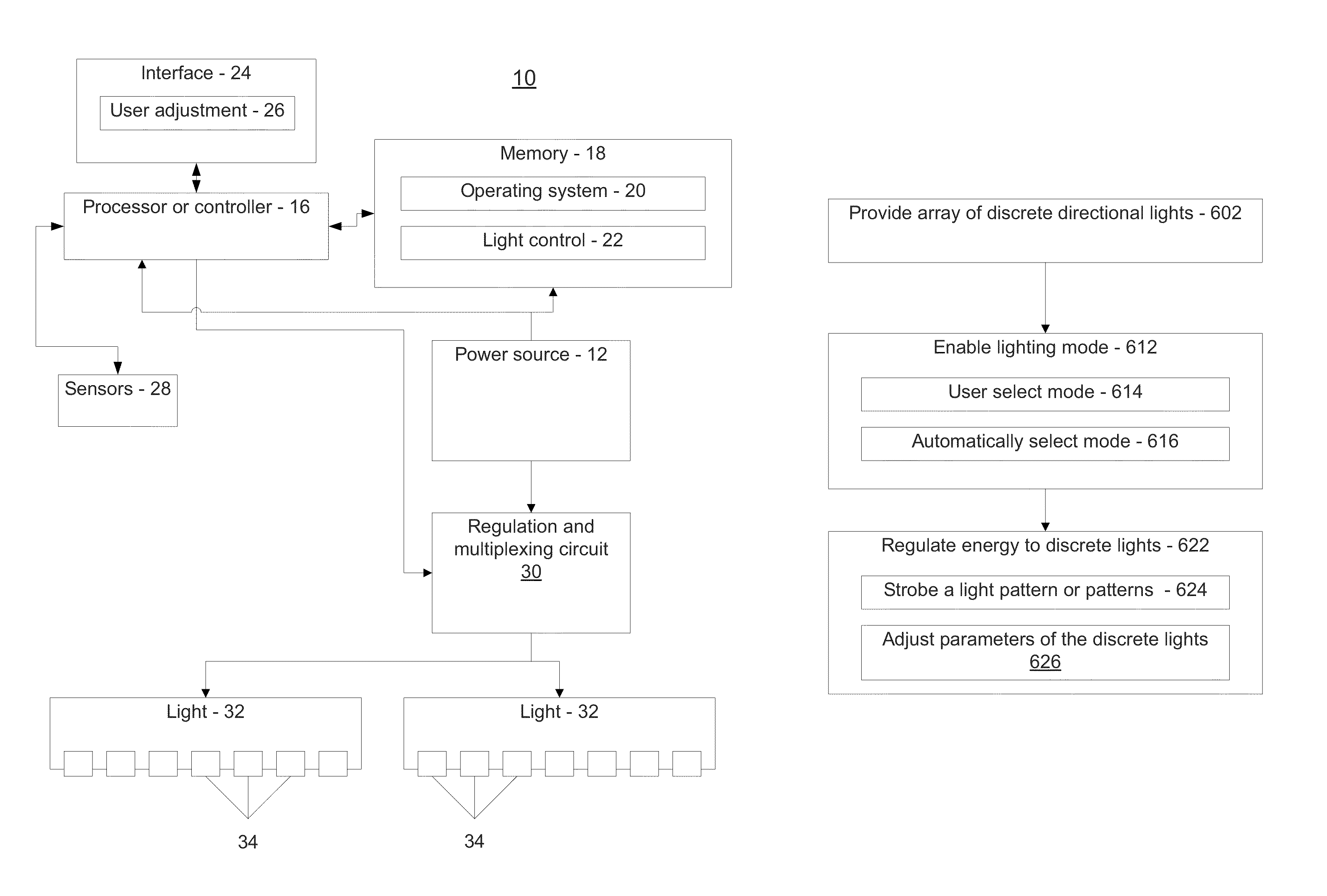
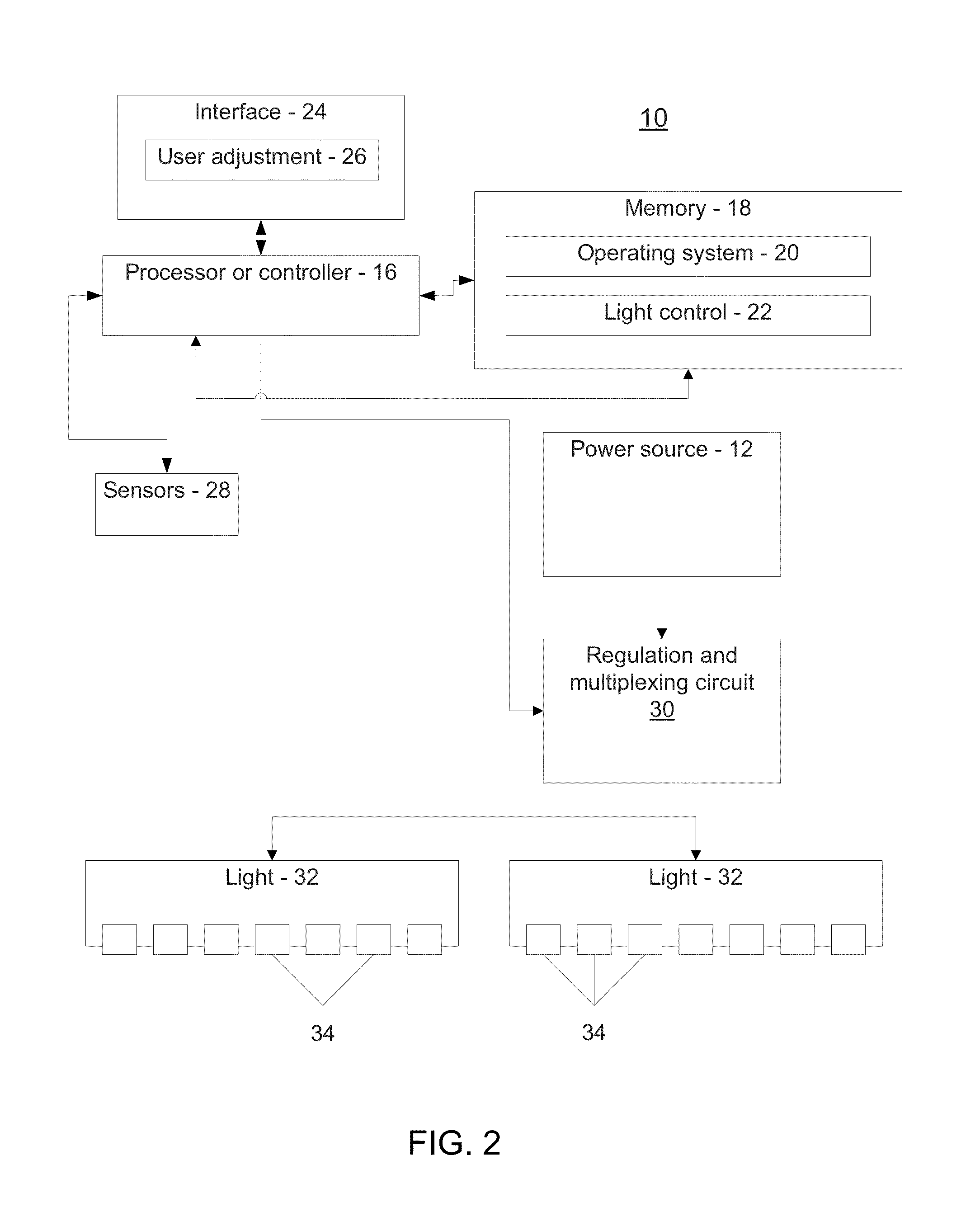
[0020]In accordance with the present principles, systems, apparatuses and methods are described, which provide strobing illumination to improve visibility during inclement weather conditions, such as rain, snow, fluid spray, etc. The present principles provide an ability to switch between modes of operation to adapt to different visibility conditions, e.g., illuminate in a first mode during snow and rain and differently during dry weather.

[0021]In a particularly useful embodiment, discreet light emission sources, such as e.g., light emitting diodes may be configured in an array. The entire array or portions thereof are configured to be strobed at a particular frequency to eliminate effects of fluid streaking on a windshield or other transparent viewing surface. Blurred images (streaking) are the effects of snow and rain falling in front of an automobile, day or night. Daytime streaking is caused by ambient light. Nighttime streaking is caused by the ambient light created by headligh...


PUM


Abstract

A light providing improved visibility during adverse conditions includes an array of discrete lights distributed over a surface. The discrete lights are configured to distribute directional light over a three-dimensional space. A regulation and multiplexing circuit is coupled to the array of discrete lights and configured to power discrete lights such that the regulation and multiplexing circuit strobes the discrete lights in accordance with environmental conditions to reduce or eliminate perceived streaking of precipitation or debris to improve operator visibility.

Description

BACKGROUND[0001]1. Technical Field[0002]The present invention relates to lighting devices, and more particularly to lighting devices and methods to improve visibility during debris fall, precipitation or adverse weather conditions.[0003]2. Description of the Related Art[0004]Dispersed light in adverse driving conditions, such as rain or snow, creates streaking as depicted in FIG. 1. Streaks, rather than single particles, are perceived by a viewer due to the relative speed of a particle in light, e.g., light from a headlight of a vehicle.[0005]During inclement conditions, such as during rain or snow, visibility is greatly reduced due to dispersed light sources with reflectors. Attempts to improve visibility have included wipers for the headlights, fog lights, if available, and high beams, which can even further reduce visibility under many conditions.SUMMARY[0006]A light providing improved visibility during adverse conditions includes an array of discrete lights distributed over a su...

Claims


Application Information

Patent Timeline
Patent Type & Authority Patents(United States)
IPC IPC(8): H05B37/02B60Q1/14H05B33/08H05B44/00
CPCB60Q1/1423H05B33/0854H05B33/0872B60Q1/1415B60Q1/18B60Q2300/312H05B45/10
Inventor REFIOR, TIMOTHYCURTIS, CHRISTIAN
Owner ARROW ELECTRONICS
Why Eureka
Try Eureka