Automation test wire of photoelectric detector

A photoelectric detector, automated testing technology, applied in the direction of instruments, etc., can solve problems such as operation errors, low operation efficiency, safety accidents, etc., achieve the effect of high degree of automation, improve safety operation coefficient, and avoid potential safety hazards

Active Publication Date: 2017-12-22
南京冠鼎光电科技有限公司
View PDF15 Cites 1 Cited by
  • Summary
  • Abstract
  • Description
  • Claims
  • Application Information

AI Technical Summary

Problems solved by technology

In the existing photodetector manufacturing process, batch quality inspection of photodetectors is an important part of the production process. The existing photodetector quality inspection equipment passes the upper jig plate 2 and the lower jig plate 3 Fix the photodetector in the jig, apply light to the photodetector, and process the output signal of the photodetector to determine whether the photodetector meets the factory standard. , the lower fixture plate 3 is fixed on the frame 1, and the upper fixture plate 2 is vertically slid and installed on the frame, so it is necessary to manually place the photodetector on the lower fixture plate and control the upper fixture The plate moves downward to realize the positioning of the photodetector, but in this operation mode, it is easy to cause the upper fixture plate to press down on the operator's arm due to operational errors or equipment failures, resulting in safety accidents; Less efficient operation on the lower fixture plate

Method used


Image

  • Automation test wire of photoelectric detector
  • Automation test wire of photoelectric detector
  • Automation test wire of photoelectric detector

Examples


Embodiment Construction

[0014] The present invention will be further described in detail below in conjunction with the accompanying drawings and examples. The following examples are explanations of the present invention and the present invention is not limited to the following examples.

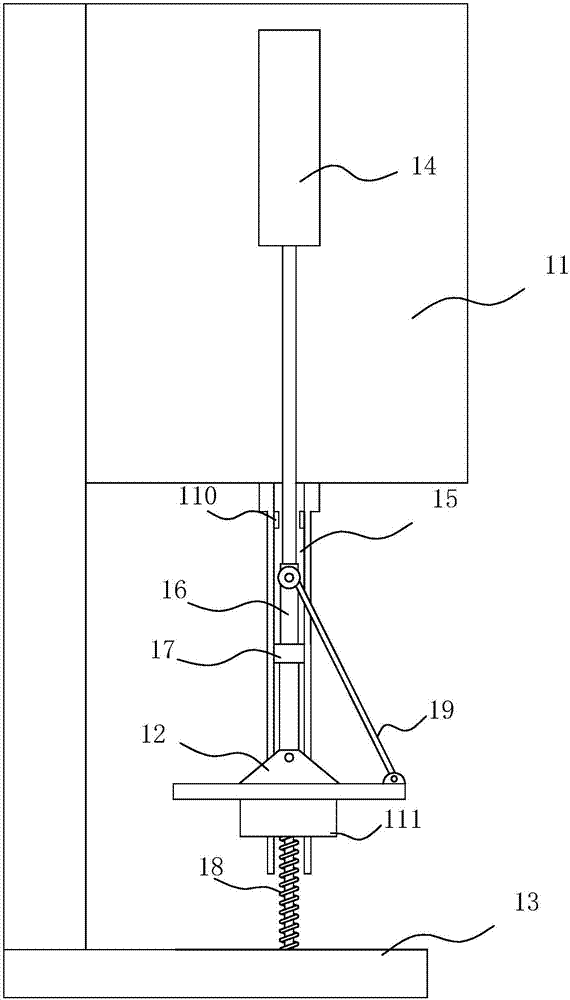
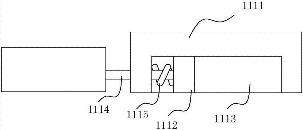
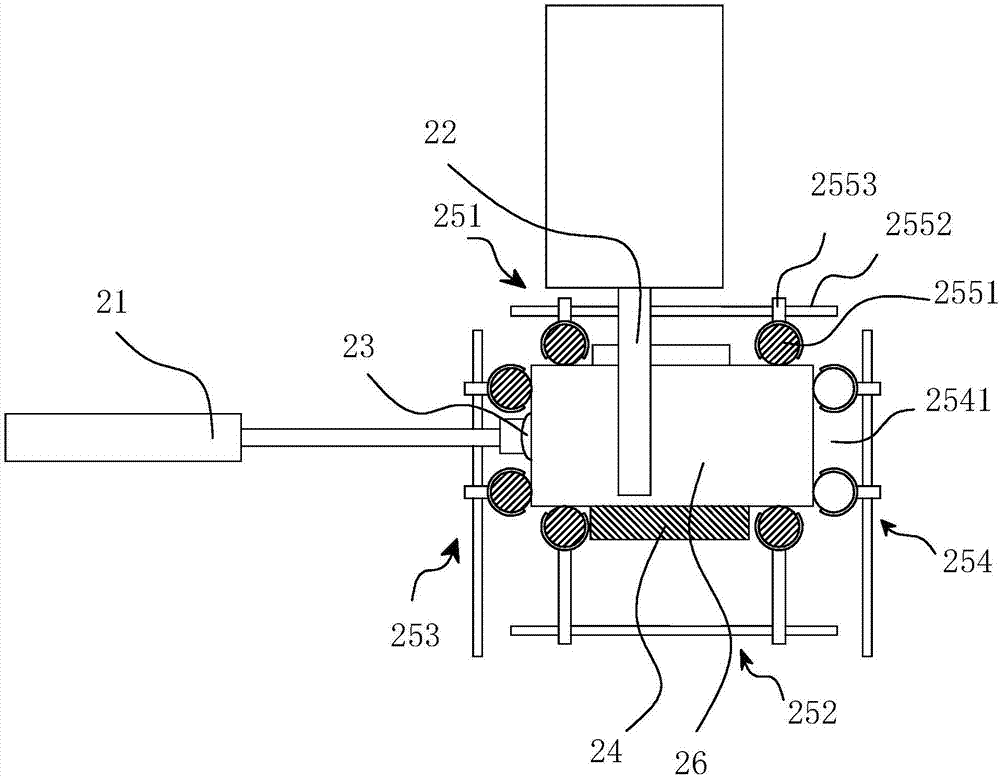
[0015] see Figure 1-Figure 4 , the photoelectric detector automatic test line of this embodiment includes a detection fixture and an automatic push track, and the detection fixture includes a frame, an upper fixture plate 12, and a lower fixture plate 13, and the lower fixture plate 13 is fixed on the frame. It is characterized in that: the two sides of the upper fixture plate 12 are respectively provided with a set of driving mechanisms, and the driving mechanism includes a cylinder 14, a guide rail 15, a lower movable block 16, an upper movable block 17, a compression spring 18 and a connecting rod 19. The cylinder body of the cylinder 14 is fixed on the frame, the guide rail 15 is vertically arranged, the lower ...


PUM


Abstract

The present invention discloses an automation test wire of a photoelectric detector. The test wire comprises a detection tool and an automatic push track, the detection tool comprises a rack, an upper tool plate and a lower tool plate, the lower tool plate is fixed on the rack, the two sides of the upper tool plate are respectively provided with one set of driving mechanism, each driving mechanism comprises a cylinder, a guiding track, a lower movable block, an upper movable block, a pressure spring and a connection rod, and the automatic push track comprises a first track cylinder, a second track cylinder, a pneumatic track sucker, a track conveyer belt and a track structure. Operators can directly put the photoelectric detector into a grip slipper from the right side to avoid hidden troubles caused by an original design, improve the safety operation coefficients, improve the operation field of vision and allow the operation to be more convenient and rapid. The automation test wire of the photoelectric detector can automatically push the photoelectric detector into the tool, is high in automation degree, can realize reciprocating motion of the photoelectric detector and can greatly improve detection efficiency.

Description

technical field [0001] The invention relates to an automatic test line for a photoelectric detector. Background technique [0002] The principle of a photodetector is that radiation causes a change in the conductivity of the irradiated material. Photodetectors are widely used in various fields of military and national economy. In the visible or near-infrared band, it is mainly used for ray measurement and detection, industrial automatic control, photometry, etc.; in the infrared band, it is mainly used for missile guidance, infrared thermal imaging, infrared remote sensing, etc. Another application of the photoconductor is to use it as the target surface of the camera tube. In order to avoid image blur caused by the diffusion of photogenerated carriers, high-resistance polycrystalline materials, such as PbS-PbO, Sb2S3, etc., are used on the continuous film target surface. Other materials can adopt the method of inlaying the target surface, and the entire target surface is...

Claims


Application Information

Patent Timeline
Patent Type & Authority Applications(China)
IPC IPC(8): G01D18/00
CPCG01D18/00Y02E10/50
Inventor 张廷志
Owner 南京冠鼎光电科技有限公司
Why Eureka
Try Eureka