Image display apparatus and head-mounted display

a display apparatus and display head technology, applied in the field of image display apparatus and head-mounted display, can solve the problems of large and heavy display apparatus as a whole easy to damage the display head, etc., and achieve the effect of increasing size and weight, reducing the risk of damage, and being easy to handl

Inactive Publication Date: 2009-07-02
KONICA MINOLTA INC
View PDF4 Cites 24 Cited by
  • Summary
  • Abstract
  • Description
  • Claims
  • Application Information

AI Technical Summary

Benefits of technology

[0041]With this structure, it is possible to view a bright image and a bright and natural outside world. In addition, as a result of the hologram optical element not being exposed, it is easy to handle the hologram optical element.
[0042]According to still another aspect of the present invention, a head-mounted display is provided with any one of the image display apparatuses described above and a supporting member supporting the image display apparatus in front of a viewer's eye. This makes possible mounting on the head.
[0043]Preferably, in the head-mounted display described above, the supporting member includes a pair of temples, each making contact with a temporal region of the viewer, a frame that pivotally supports the temples and supports the image display apparatus, and nose pads that are brought into contact with a nose of the viewer. This makes it possible to wear the head-mounted display like eyeglasses.
[0044]According to the present invention, the use of the sealing member makes it possible to fill the gap between the enclosure and the prism and the gap in the joint of the enclosure components without incurring any increase in size and weight, and thereby makes the apparatus resistant to water and dust.

Problems solved by technology

However, the technique disclosed in JP-A-H11-296095, although it helps keep the inside of the image display portion dust free, makes the display apparatus as a whole large and heavy, making it difficult for the user to use it for a long time.
On the other hand, in the technique disclosed in JP-A-H9-318905, the enclosure and the lens are simply joined together, making the joint between them vulnerable to dust and water.

Method used


Image

  • Image display apparatus and head-mounted display
  • Image display apparatus and head-mounted display
  • Image display apparatus and head-mounted display

Examples


Embodiment Construction

1. HMD

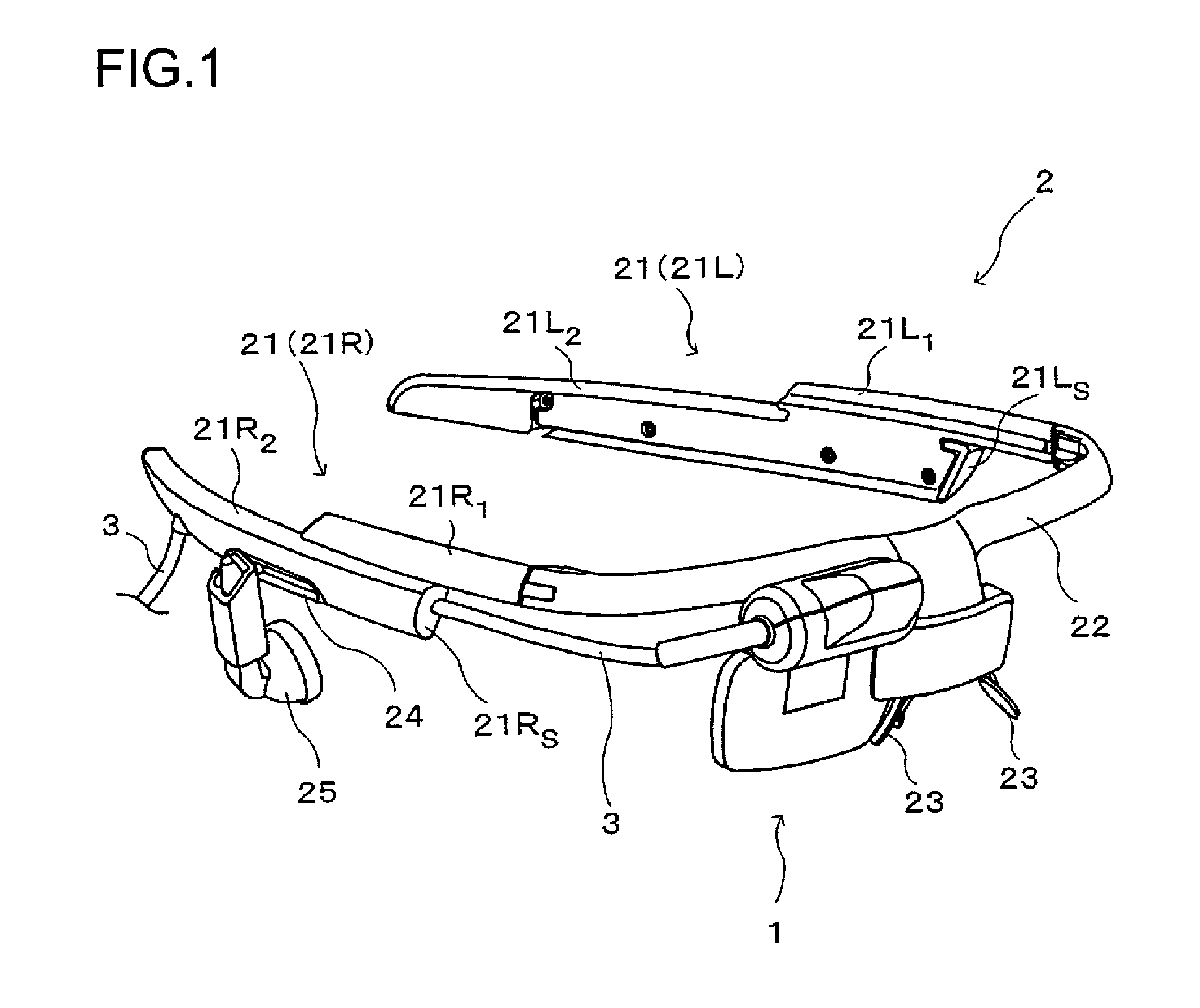
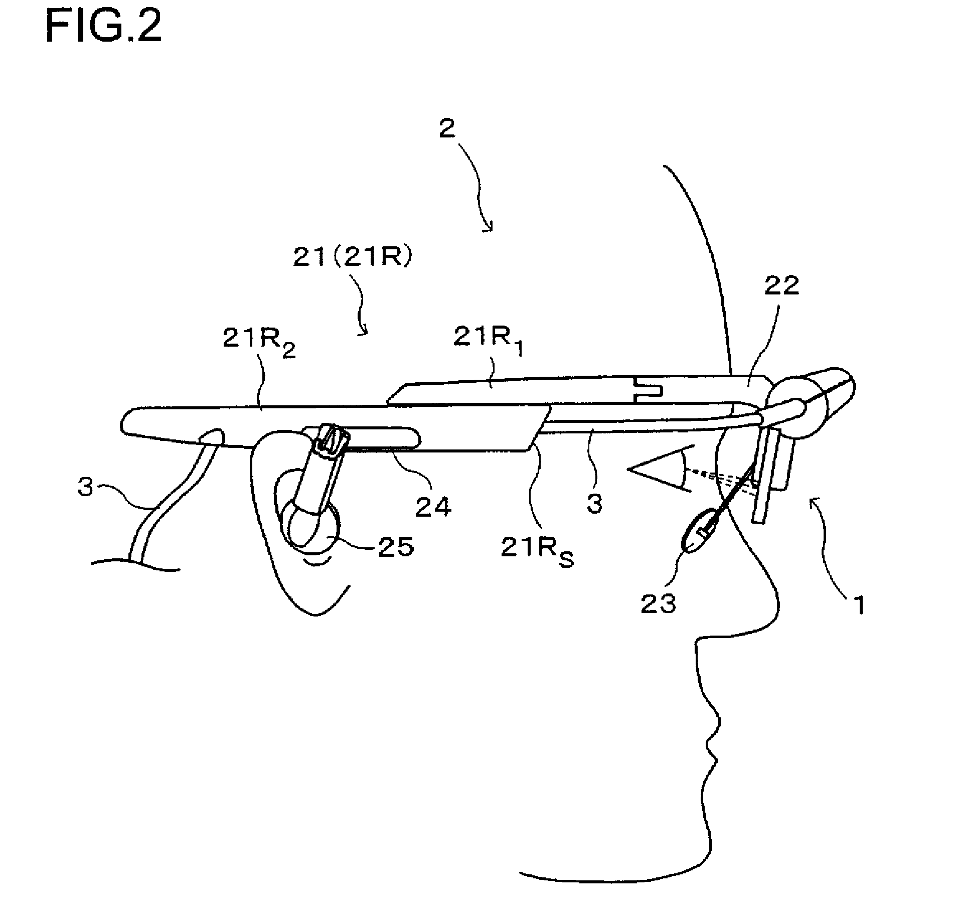
[0056]FIG. 1 is a perspective view showing an outline of the structure of a HMD according to an embodiment, and FIG. 2 is a side view of the HMD worn by the viewer. The HMD is composed of an image display apparatus 1, a supporting member 2, and a cable 3.

[0057]The image display apparatus 1 displays an image and presents it to the viewer. The supporting member 2 supports the image display apparatus 1 in front of the viewer's eye. In this embodiment, the supporting member 2 supports the image display apparatus 1 in such a way that the image display apparatus 1 is positioned in front of the viewer's right eye. However, it is also possible to provide two image display apparatuses 1, and support them in such a way that they are positioned in front of the eyes. In either case, as a result of the image display apparatus 1 being supported by the supporting member 2, the viewer is allowed to view an image displayed by the image display apparatus 1 with both hands free. The cable 3 conn...


PUM


Abstract

Provided is an image display apparatus that has resistance to dust and water, that is compact and lightweight, and that has see-through characteristics. The image display apparatus is provided with a display device displaying an image, a prism guiding light of the image displayed by the display device to an optical pupil, and transmitting outside light such that an outside world can be viewed therethrough, and an enclosure housing and holding the display device and part of the prism. Here, a first sealing member is provided so as to make contact with a part around the prism where image light is not reflected and with the enclosure.

Description

[0001]This application is based on Japanese Patent Applications Nos. 2007-338438 and 2007-338453 both filed on Dec. 28, 2007, the contents of which are hereby incorporated by reference.BACKGROUND OF THE INVENTION[0002]1. Field of the Invention[0003]The present invention relates to image display apparatuses that present a viewer with an image displayed by a display device as a virtual image, and head-mounted displays (hereinafter also referred to as “HMDs”) provided with such image display apparatuses.[0004]2. Description of Related Art[0005]To date, various so-called HMDs, head-mounted image display apparatuses, have been proposed. Recently, HMDs are beginning to be used not just in general consumer goods, but for the purpose of assisting the user in carrying out operations smoothly by providing various information for the user. Depending on the environment in which the HMDs will be used, they are required to have a function that is not needed when used as general consumer goods. Fo...

Claims


Application Information

Patent Timeline
Patent Type & Authority Applications(United States)
IPC IPC(8): G02B5/32
CPCG02B27/0176G02B27/017
Inventor YAMAGUCHI, HIROSHITANIJIRI, YASUSHI
Owner KONICA MINOLTA INC
Why Eureka
Try Eureka